Ditch bottom sludge clearing machine for hydraulic engineering and clearing method

A water conservancy project and cleaning machine technology, which is applied in the direction of earth mover/shovel, mechanically driven excavator/dredger, construction, etc. It can solve the problems of large scale of water conservancy projects, environmental impact, long construction period, etc.

Active Publication Date: 2020-11-13
王军民 +2
View PDF10 Cites 1 Cited by
  • Summary
  • Abstract
  • Description
  • Claims
  • Application Information

AI Technical Summary

Problems solved by technology

[0006] ② have a great impact on the environment;
[0007] ③Complicated working conditions;
[0008] ④ The benefits of water conservancy projects are random;
[0009] ⑤Water conservancy projects are generally large in scale, complex in technology, long in construction period and high in investment, and must be constructed in accordance with basic construction procedures and relevant standards
However, the inventor found out that due to the large amount of silt and the high viscosity after settling, it is necessary to give the silt suction machine enough time to ensure the cleaning effect, so it needs to stop and go, and it is troublesome to control

Method used


Image

  • Ditch bottom sludge clearing machine for hydraulic engineering and clearing method
  • Ditch bottom sludge clearing machine for hydraulic engineering and clearing method
  • Ditch bottom sludge clearing machine for hydraulic engineering and clearing method

Examples


Embodiment 1

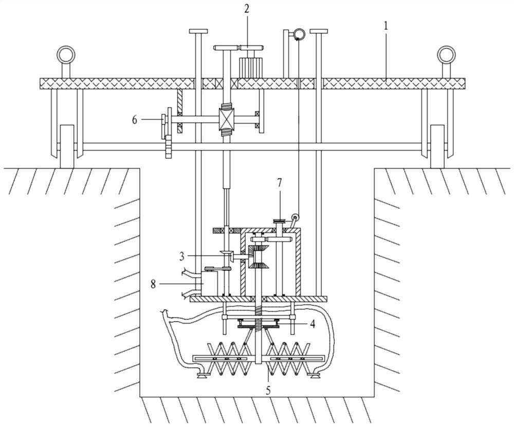
[0074] With reference to the accompanying drawings, a canal bottom sludge cleaning machine for water conservancy projects includes a car body assembly 1, a drive assembly 2, a reciprocating assembly 3, a push-pull assembly 4, a mud mixing assembly 5, and a walking assembly 6;

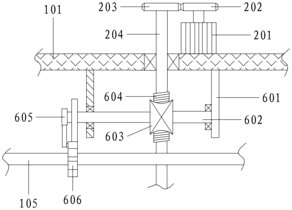
[0075] The vehicle body assembly 1 includes a vehicle plate 101, lifting lugs 102, wheel frames 103, wheels 104, wheel axles 105, a type of connecting rod 106 and a type of support plate 107; The four corners of the bottom of 101 are fixedly connected with a wheel frame 103, and the wheel frame 103 is connected with a wheel 104 through a wheel shaft 105. The two wheels 104 on the front side are mounted on the same wheel shaft 105, and the two wheels 104 on the rear side are mounted on the same wheel shaft 105. A wheel shaft 105 is provided with a walking assembly 6; a driving assembly 2 is provided on the vehicle board 101, and the walking assembly 6 is connected to the driving assembly 2;

[0076] A ty...

Embodiment 2

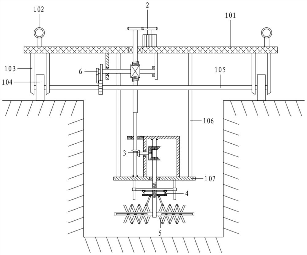
[0078] With reference to the accompanying drawings, a canal bottom sludge cleaning machine for water conservancy projects includes a car body assembly 1, a drive assembly 2, a reciprocating assembly 3, a push-pull assembly 4, a mud mixing assembly 5, and a walking assembly 6;

[0079] The vehicle body assembly 1 includes a vehicle plate 101, lifting lugs 102, wheel frames 103, wheels 104, wheel axles 105, a type of connecting rod 106 and a type of support plate 107; The four corners of the bottom of 101 are fixedly connected with a wheel frame 103, and the wheel frame 103 is connected with a wheel 104 through a wheel shaft 105. The two wheels 104 on the front side are mounted on the same wheel shaft 105, and the two wheels 104 on the rear side are mounted on the same wheel shaft 105. A wheel shaft 105 is provided with a walking assembly 6; a driving assembly 2 is provided on the vehicle board 101, and the walking assembly 6 is connected to the driving assembly 2;

[0080] A ty...

Embodiment 3

[0102] The difference from Embodiment 2 is that the position of the support plate 107 of this embodiment is adjustable.

[0103] In this embodiment, the top end of the first type of connecting rod 106 is not connected to the vehicle plate 101 as in Embodiment 2, and the bottom end of the first rotating shaft 204 is not connected to the top of the second rotating shaft 205 as in Embodiment 2;

[0104] It also includes a lifting assembly 7; the lifting assembly 7 includes a steel wire rope 706, a tether ring 707, a fixed rod 708, a spline shaft 709 and a shaft sleeve 710;

[0105] The bottom end of a first-class connecting rod 106 is connected with a first-class support plate 107, and the top vertically passes through the vehicle plate 101 and is fixedly connected with an anti-off plate 108; a fixed rod 708 is connected above the vehicle plate 101, and a tether is fixedly connected to the fixed rod 708 Ring 707; the top end of the wire rope 706 is connected to the tether ring 70...


PUM


Abstract

The invention relates to the technical field of ditch bottom sludge clearing, in particular to a ditch bottom sludge clearing machine for hydraulic engineering and a clearing method. A servo motor isadopted to drive a driving assembly to work, and a fifth rotating shaft rotates; a driving plate on the fifth rotating shaft rotates along with the fifth rotating shaft and intermittently rotates through a sheave, so that a wheel shaft drives wheels to synchronously rotate, and intermittent automatic advancing of the clearing machine is achieved; a first bevel gear on a second rotating shaft rotates immediately, and a second bevel gear drives a coaxial incomplete bevel gear to rotate through bevel gear transmission; the incomplete bevel gear is in intermittent fit with a driven bevel gear, sothat a fourth rotating shaft rotates forwards and reversely in a reciprocating manner; a sludge stirring assembly stirs sludge at the bottom of a ditch along with rotation of the fourth rotating shaft, so that the sludge can flow away along with water flow conveniently, and the sludge is cleared; and in cooperation with intermittent advancing of a travelling assembly, an automatic parking time period is reserved for the clearing machine, and the sludge is effectively stirred.

Description

technical field [0001] The invention relates to the technical field of canal bottom sludge cleaning, in particular to a canal bottom sludge cleaning machine and a cleaning method for water conservancy projects. Background technique [0002] Water conservancy projects are projects built to control and allocate natural surface water and groundwater to achieve the purpose of eliminating harm and rejuvenating profits. Also known as water engineering. [0003] Water is an indispensable precious resource for human production and life, but its natural state does not fully meet human needs. Only by building water conservancy projects can we control water flow, prevent floods, and regulate and distribute water to meet the needs of people's life and production for water resources. [0004] Water conservancy projects have the following characteristics: [0005] ① Strongly systematic and comprehensive; [0006] ② have a great impact on the environment; [0007] ③Complicated working...

Claims


Application Information

Patent Timeline
IPC IPC(8): E02F5/28E02F3/88E02F3/90E02F3/92
CPCE02F5/282E02F3/8816E02F3/905E02F3/9281E02F3/9293
Inventor 王军民史宏智王昭鹏
Owner 王军民
Why Eureka
Try Eureka