Intelligent sensor prototype testing device

A technology for intelligent sensor and prototype testing, which is applied in the direction of measuring devices, instruments, calibration/testing of force/torque/power measuring instruments, etc., and can solve problems such as difficulty in stabilizing the horizontal direction of the device, difficulty in determining the tension sensor, and large errors. Achieving a high degree of accuracy

Pending Publication Date: 2020-11-13
国网江西省电力有限公司宜春供电分公司 +2
View PDF1 Cites 0 Cited by
  • Summary
  • Abstract
  • Description
  • Claims
  • Application Information

AI Technical Summary

Problems solved by technology

The existing intelligent sensor prototype test device has the following problems: it is often difficult to control the horizontal direction of the device to be stable when measuring the existing tension sensor, and the error is large when measuring, and it is difficult to determine whether the tension sensor is qualified. Patents are not easy to solve such problems, therefore, there is an urgent need for a smart sensor prototype test device to solve the above problems

Method used


Image

  • Intelligent sensor prototype testing device
  • Intelligent sensor prototype testing device
  • Intelligent sensor prototype testing device

Examples


Embodiment 1

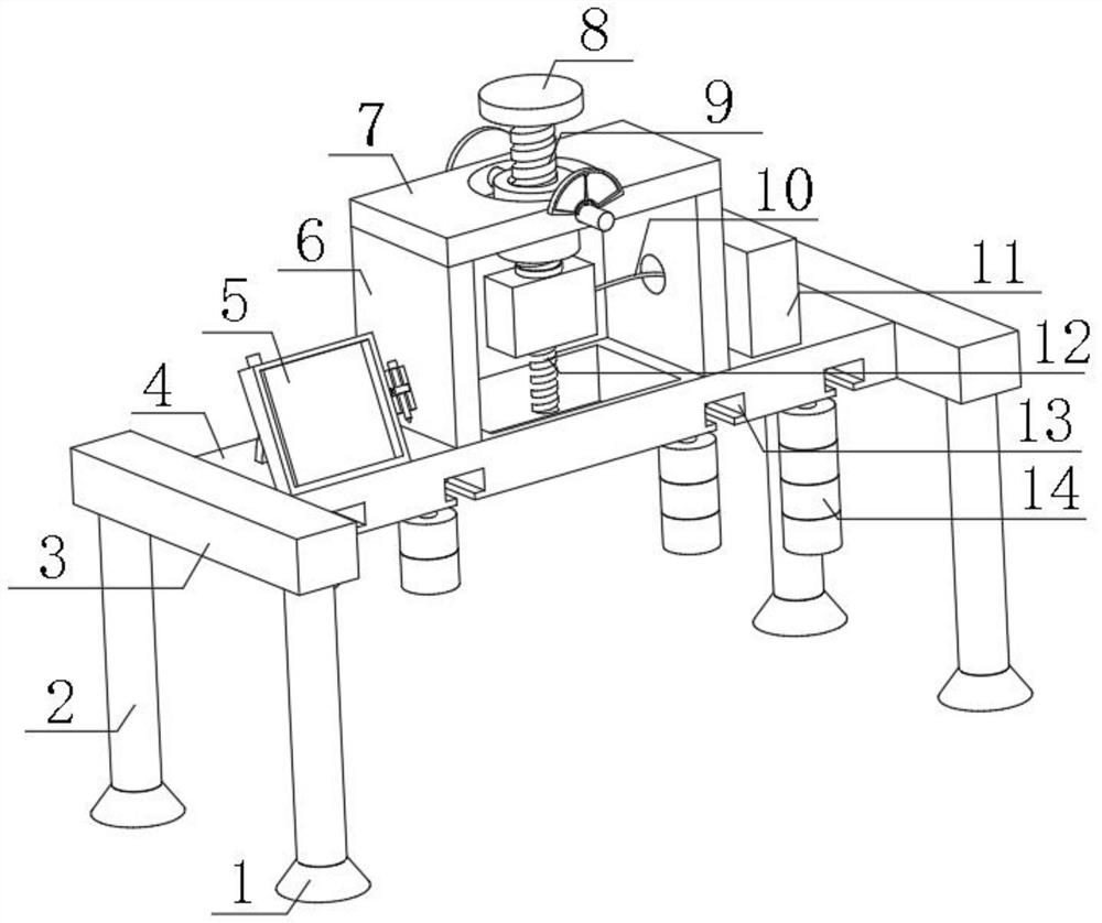
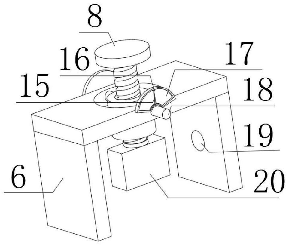
[0027] refer to Figure 1-4 , a smart sensor prototype test device, comprising a bottom plate 4, the central position of the top outer wall of the bottom plate 4 is fixedly connected with two support plates 6 by bolts, and the same horizontal plate 7 is fixedly connected on the top outer walls of the two support plates 6, and the horizontal plate 7 The central position of the outer wall of the top of the plate 7 is provided with a mounting hole, and the outer walls of both sides of the horizontal plate 7 are inserted with rotating rods 18, and the opposite ends of the two rotating rods 18 are fixedly connected with the same threaded sleeve, and the inner wall of the threaded sleeve is threaded. Connected with a first threaded rod 9, the top of the first threaded rod 9 is fixedly connected with a knob 8, the outer walls of both sides of the horizontal plate 7 are fixedly connected with finger plates 17, and the inner walls of one side of the two finger plates 17 are provided wit...

Embodiment 2

[0036] refer to Figure 5, a smart sensor prototype test device, comprising a bottom plate 4, the central position of the top outer wall of the bottom plate 4 is fixedly connected with two support plates 6 by bolts, and the same horizontal plate 7 is fixedly connected on the top outer walls of the two support plates 6, and the horizontal plate 7 The central position of the outer wall of the top of the plate 7 is provided with a mounting hole, and the outer walls of both sides of the horizontal plate 7 are inserted with rotating rods 18, and the opposite ends of the two rotating rods 18 are fixedly connected with the same threaded sleeve, and the inner wall of the threaded sleeve is threaded. Connected with a first threaded rod 9, the top of the first threaded rod 9 is fixedly connected with a knob 8, the outer walls of both sides of the horizontal plate 7 are fixedly connected with finger plates 17, and the inner walls of one side of the two finger plates 17 are provided with ...


PUM


Abstract

The invention discloses an intelligent sensor prototype testing device. For the problem that the stability of a device in the horizontal direction is difficult to control and errors are large during measurement, the invention presents the following solution that the device comprises a bottom plate, two supporting plates are fixedly connected to the center of the outer wall of the top of the bottomplate through bolts, the outer walls of the tops of the two supporting plates are fixedly connected with the same transverse plate, an installation hole is formed in the center of the outer wall of the top of the transverse plate, rotating rods are inserted into the outer walls of the two sides of the transverse plate, the opposite ends of the two rotating rods are fixedly connected with the samethreaded sleeve, the inner wall of the threaded sleeve is in threaded connection with a first threaded rod, and the top end of the first threaded rod is fixedly connected with a rotary knob. A benchmark on a finger disc can be matched with pointers on the outer walls of sides of the rotating rods to visually see whether the device is placed flatly or not, the device is placed flatly in time before a sensor prototype is tested, and the high accuracy of a measurement result is guaranteed.

Description

technical field [0001] The invention relates to the technical field of sensor prototype testing, in particular to an intelligent sensor prototype testing device. Background technique [0002] At present, the tension sensor is one of the components often used in mechanical production activities. Before leaving the factory, the tension sensor generally needs to be inspected randomly to test whether the tension sensor meets the standard. Tension sensor, also known as resistance strain sensor, belongs to the load cell series. It uses two tension transmission parts to transmit force, and its structure contains force-sensitive devices and two tension transmission parts. The force-sensing devices contain piezoelectric sheets, piezoelectric sheet gaskets, and the latter contains substrate parts and edge force transmission parts. Part, which is characterized in that the two ends of the two tension transmission parts are respectively fixed together, and the force-sensitive device is ...

Claims


Application Information

Patent Timeline
Patent Type & Authority Applications(China)
IPC IPC(8): G01L25/00
CPCG01L25/00
Inventor 刘耀华肖燕李超刘广刘晖刘清华袁晓霞
Owner 国网江西省电力有限公司宜春供电分公司
Why Eureka
Try Eureka