U-shaped circulating convection wing plate propelling device

A technology of propulsion device and wing plate, which is applied in ship propulsion, propulsion components, transportation and packaging, etc., can solve the problems of vibration, noise and cavitation, increase the target intensity of ship wake, and conceal unfavorable targets, so as to reduce vibration or noise. , The effect of compact structure and convenient layout

Active Publication Date: 2020-11-17
CHINA SHIP SCIENTIFIC RESEARCH CENTER (THE 702 INSTITUTE OF CHINA SHIPBUILDING INDUSTRY CORPORATION)
View PDF7 Cites 0 Cited by
  • Summary
  • Abstract
  • Description
  • Claims
  • Application Information

AI Technical Summary

Problems solved by technology

[0003] The propeller propeller has the advantage of high propulsion efficiency, but it has inherent deficiencies in the control of vibration, noise, and cavitation. In water, it is easy to cause vibration, noise and cavitation problems; in addition, during the rotation of the propeller, a part of the energy will inevitably be brought into the wake, such as cavitation on the surface of the blade, which is easy to transmit the air bubbles to the far rear, increasing the The strength of the trailing target is not conducive to its target concealment

Method used


Image

  • U-shaped circulating convection wing plate propelling device
  • U-shaped circulating convection wing plate propelling device
  • U-shaped circulating convection wing plate propelling device

Examples


Embodiment Construction

[0030] The specific implementation manner of the present invention will be described below in conjunction with the accompanying drawings.

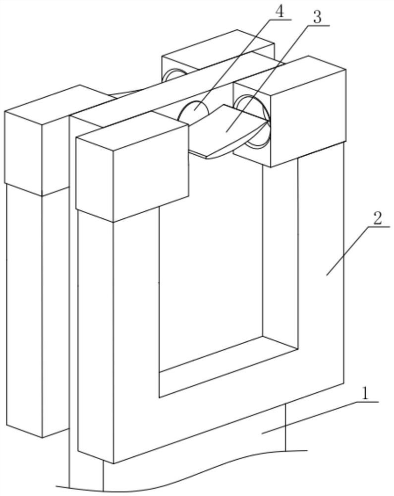
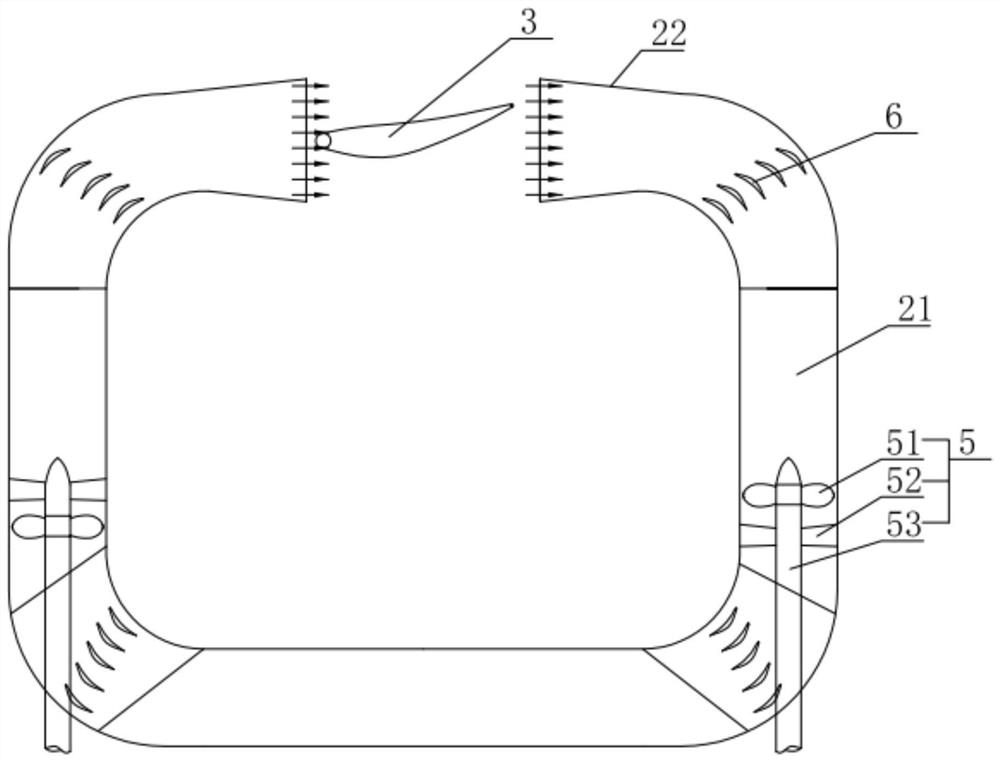
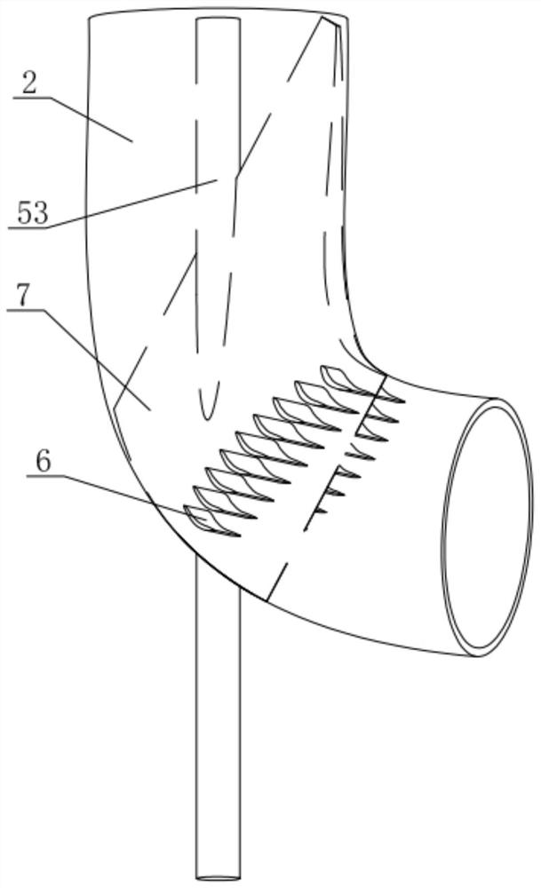
[0031] like figure 1 and figure 2 As shown, the U-shaped circulation convection flap propulsion device of the present embodiment includes a circulation pipeline 2 with an integral hollow structure, and the openings at both ends of the circulation pipeline 2 are arranged at relative intervals; A wing plate 3 is installed in the interval, and an adjustment seat 4 is installed at the end of the wing plate 3. The axis direction of the wing plate 3 swinging with the adjustment seat 4 is perpendicular to the line connecting the openings at both ends of the circulation pipeline 2; the inside of the circulation pipeline 2 is along the One or more sets of axial flow pumps 5 are arranged in the axial direction, and the openings at both ends of the circulation pipeline 2 are the inlet and outlet ports respectively. Under the action of the axial flo...


PUM


Abstract

The invention relates to a U-shaped circulating convection wing plate propelling device which comprises a circulating pipeline with an integrated hollow structure, and openings in the two ends of thecirculating pipeline are oppositely formed at intervals. A wing plate is mounted in a gap between openings in the two ends of the circulating pipeline, an adjusting seat is mounted at the end of the wing plate, and the swing axis direction of the wing plate along with the adjusting seat is perpendicular to the connecting line of the openings in the two ends of the circulating pipeline; wherein oneor more groups of axial flow pumps are arranged in the circulating pipeline along the axial direction, openings at two ends of the circulating pipeline are respectively an inlet end and an outlet end, under the action of the axial flow pumps, fluid flows out from the outlet end after entering from the inlet end of the circulating pipeline and then enters from the inlet end through the wing platesto form circulation, and the circulating fluid generates a thrust force to the wing plates. Therefore, when most of fluid circularly flows in the pipeline to generate thrust, the wake characteristicof an existing propeller is effectively restrained, and the low-noise and quiet operation of the propelling device is greatly assisted.

Description

technical field [0001] The invention relates to the technical field of underwater navigation propellers, in particular to a U-shaped circulation convection vane propulsion device. Background technique [0002] In the prior art, a ship or an underwater vehicle mainly converts mechanical energy into kinetic energy for the ship to advance through a rotating part—the propeller. force. [0003] The propeller propeller has the advantage of high propulsion efficiency, but it has inherent deficiencies in the control of vibration, noise, and cavitation. In water, it is easy to cause vibration, noise and cavitation problems; in addition, during the rotation of the propeller, a part of the energy will inevitably be brought into the wake. The strength of the trailing target is not conducive to its target concealment. Contents of the invention [0004] Aiming at the shortcomings in the above-mentioned existing production technology, the applicant provides a U-shaped circulation conv...

Claims


Application Information

Patent Timeline
Patent Type & Authority Applications(China)
IPC IPC(8): B63H19/00
CPCB63H19/00
Inventor 周斌樊晓冰李亮唐登海翟树成
Owner CHINA SHIP SCIENTIFIC RESEARCH CENTER (THE 702 INSTITUTE OF CHINA SHIPBUILDING INDUSTRY CORPORATION)
Why Eureka
Try Eureka