Automatic spindle mounting and pulling and paper tube sleeving mechanism

A paper tube and shaft threading technology, which is applied in the field of automatic shaft pulling and shaft threading mechanism, can solve the problems of high labor intensity, many personnel and low efficiency, and achieve the effect of reducing labor intensity and saving personnel.

Pending Publication Date: 2020-11-17
CHTC HEAVY IND +1
View PDF0 Cites 2 Cited by
  • Summary
  • Abstract
  • Description
  • Claims
  • Application Information

AI Technical Summary

Problems solved by technology

Therefore, the work of replacing the mandrel threading tube is not only labor-intensive and inefficient, but also requires many people per shift.

Method used


Image

  • Automatic spindle mounting and pulling and paper tube sleeving mechanism
  • Automatic spindle mounting and pulling and paper tube sleeving mechanism
  • Automatic spindle mounting and pulling and paper tube sleeving mechanism

Examples


Embodiment Construction

[0022] The present invention will be further described below in conjunction with example (accompanying drawing):

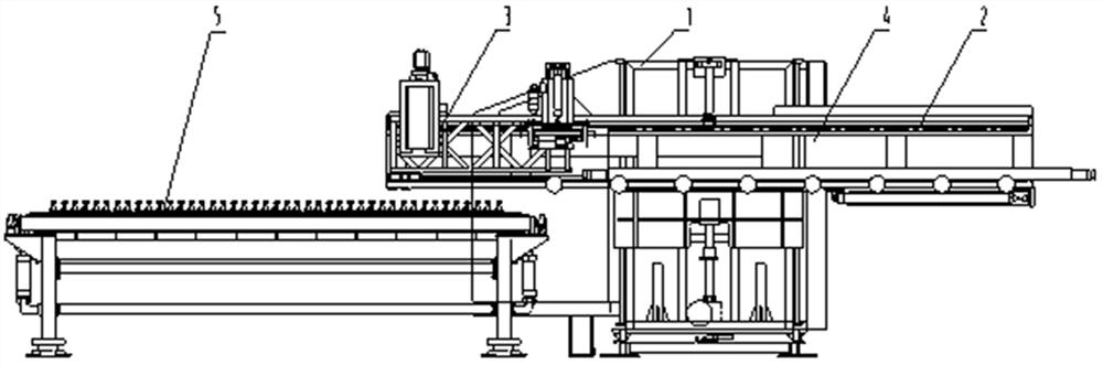
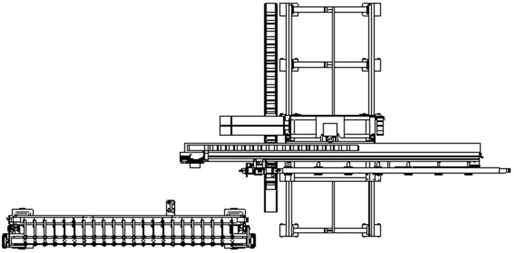
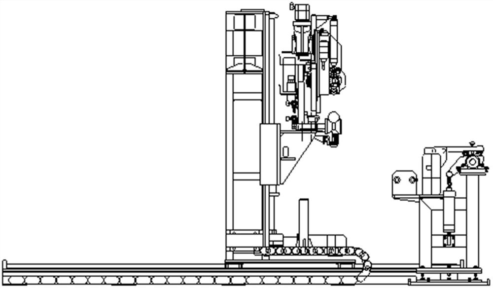
[0023] Such as Figure 1~Figure 4 As shown, the automatic upper shaft pulling shaft and paper tube mechanism of the present invention includes a stand mechanism 1 capable of moving back and forth on the track mechanism, a horizontal guide mechanism 2 installed on the stand mechanism elevator, and a horizontal guide mechanism 2 installed on the horizontal guide mechanism 2. , and the clamping inflation and deflation device 3 that can move left and right along the horizontal guide mechanism; A paper tube positioning device 5 is provided on the side.

[0024] Further, the track mechanism includes left and right horizontal guide rails 13 installed on the horizontally arranged left and right track plates 12 through fixed connectors, racks 14 arranged in parallel between the left and right guide rails, and the track plates are parallel to each other. The horizontal to...


PUM


Abstract

An automatic spindle mounting and pulling and paper tube sleeving mechanism is characterized by comprising a vertical frame mechanism capable of moving forwards and backwards on a rail mechanism, a horizontal guide mechanism mounted on a vertical frame mechanism lifter, a clamping inflating and deflating device mounted on the horizontal guide mechanism and capable of moving leftwards and rightwards along the horizontal guide mechanism, an air channel control mechanism installed on the horizontal guide mechanism, and a paper tube sleeving positioning device located on one side of the vertical frame mechanism. The mechanism is suitable for the condition that the spindle can be mounted in a splitting machine from the side face and the relative position of a cloth roll can be fixed after splitting and roll unloading; by using the mechanism, operators can be reduced, the labor intensity of workers can be greatly reduced, and automatic spindle mounting and pulling and paper tube sleeving functions of the splitting machine are achieved.

Description

technical field [0001] The invention relates to the technical field of textile technology, in particular to an automatic upper shaft pulling shaft threading paper tube mechanism suitable for a nonwoven fabric slitting machine. Background technique [0002] The slitting machine cuts the large roll into strip-shaped sub-rolls with different width specifications required by customers. Generally, the cutting speed is about 300m / min, and the higher one can reach more than 1000m / min. The diameter of the sub-roll after slitting Generally 1200mm. After slitting the sub-rolls, the mandrel must be pulled out and put back on the paper tube for later use. At present, the sub-roll mandrel after slitting and rewinding needs to be pulled out manually. Since the length of the mandrel of the wide-width slitting and winding equipment is close to 4m and the weight is about 120kg, it generally requires 2 to 4 people to assist in the operation of the mandrel each time. After pulling it out and...

Claims


Application Information

Patent Timeline
Patent Type & Authority Applications(China)
IPC IPC(8): D06H7/08B65H19/30B65H75/24
CPCB65H19/30B65H19/305B65H75/24D06H7/08
Inventor 汤水利王红波李新奇吕宏斌杜晓静赵霄龙王晓雨周素利牛亚雯
Owner CHTC HEAVY IND
Why Eureka
Try Eureka