
Cam bending mechanism

A technology of bending mechanism and cam, which is applied in the field of automatic assembly, can solve the problems of waste of cost and space, heavy workload of assembly personnel, and low efficiency, so as to ensure assembly accuracy and stability, realize automation and intelligence, and save production cost effect

Inactive Publication Date: 2014-01-08
KUNSHAN YIXIN RELIANCE PRECISION IND
View PDF3 Cites 3 Cited by
  • Summary
  • Abstract
  • Description
  • Claims
  • Application Information

AI Technical Summary

Problems solved by technology

[0002] At present, the processes involving connector terminal bending and cutting in domestic automation operations are mainly manual, and the assembly work is completed manually. The disadvantages of this working mode are that the material assembly work is cumbersome, the assembly personnel have a large workload, and the efficiency is low. , high error rate
In addition, the manual operation method often requires a large number of people and equipment, which seriously wastes cost and space, making it difficult to achieve high-quality and high-efficiency operations.

Method used


Image

  • Cam bending mechanism

Examples


Embodiment Construction

[0024] The following will clearly and completely describe the technical solutions in the embodiments of the present invention with reference to the drawings in the embodiments of the present invention.

[0025] The invention provides a cam bending mechanism, which is widely used for terminal cutting and welding in the field of automatic assembly, can realize high-quality and high-efficiency assembly of products, and has the advantages of improving production efficiency and reducing production cost.

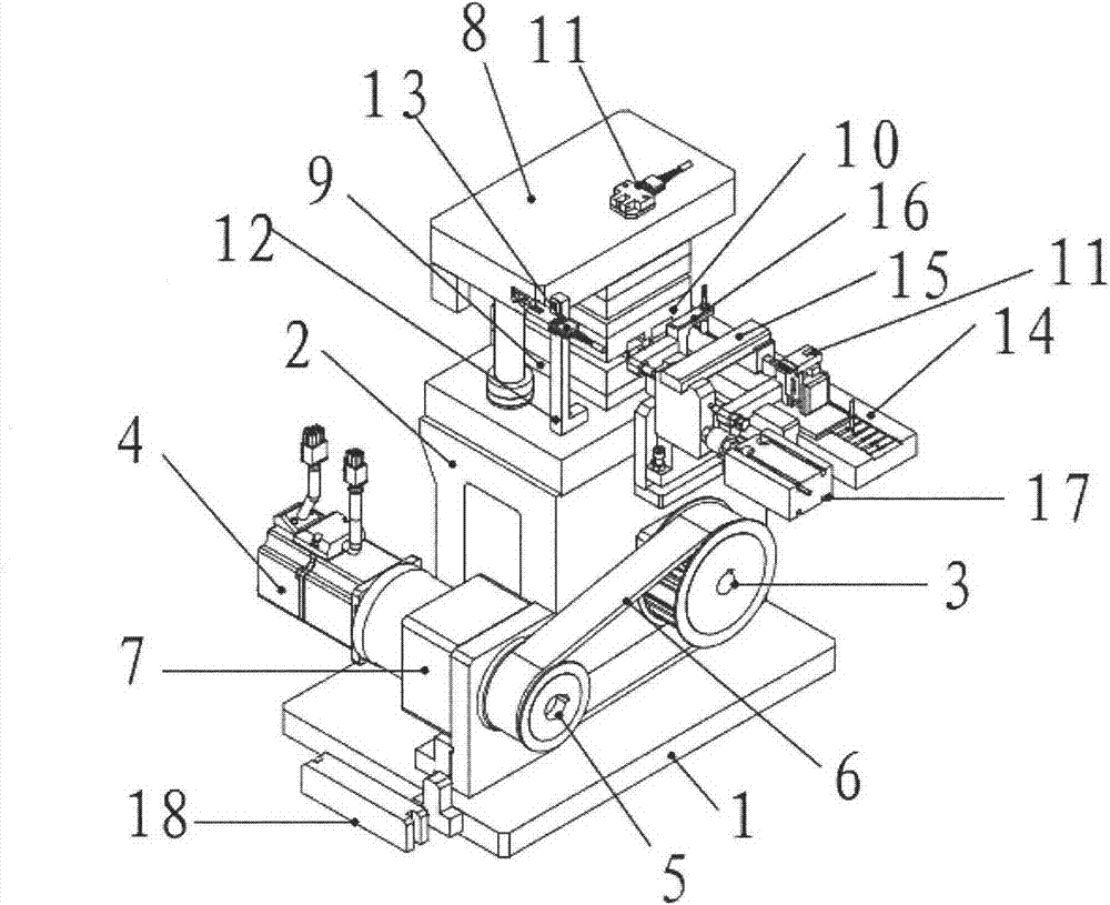
[0026] Such as figure 1 As shown, a cam bending mechanism is used in the processing and assembly process of terminals, including a base plate 1, a cam box 2 is installed above the base plate 1, and a cam is provided inside and outside the cam box 2, and the two cams cooperate with each other. synchronous rotation;

[0027] The outer cam 3 is connected to and driven by a driving device;

[0028] The inner cam (not shown in the figure) is upwardly connected with a cutting and bend...


PUM


Abstract

The invention provides a cam bending mechanism. The cam bending mechanism has the advantages that a cam is driven by a servo motor, further drives a mold to cut and bend a terminal and simultaneously is matched with a feeding device to realize automation and intelligentization of cutting and bending of the terminal, so that not only is the production efficiency improved greatly and is the production cost saved, but also the occupied area of equipment is reduced, and the assembling accuracy and the stability are ensured. Therefore, the cam bending mechanism is beneficial to long-term stable development of an enterprise.

Description

technical field [0001] The invention relates to the field of automatic assembly, in particular to a cam bending mechanism. Background technique [0002] At present, the processes involving connector terminal bending and cutting in domestic automation operations are mainly manual, and the assembly work is completed manually. The disadvantages of this working mode are that the material assembly work is cumbersome, the assembly personnel have a large workload, and the efficiency is low. , High error rate. Moreover, the manual operation method often requires a large number of people and equipment, which seriously wastes cost and space, making it difficult to achieve high-quality and high-efficiency operations. [0003] Therefore, how to reduce the labor intensity of assembly personnel, simplify labor complexity, improve work efficiency, and improve the quality and efficiency of the assembly process is a research topic with far-reaching significance. Contents of the invention ...

Claims


Application Information

Patent Timeline
IPC IPC(8): H01R43/16B21F1/00B21F11/00
Inventor 刘春节满军
Owner KUNSHAN YIXIN RELIANCE PRECISION IND
Learn More