Paint uniform brushing device for iron bucket

A technology for paint and iron buckets, which is applied in the field of iron bucket paint brushing devices, which can solve the problems of uneven manual painting and waste of paint, and achieve the effect of conveniently putting in and taking out iron buckets and saving paint

Active Publication Date: 2020-11-20
淮北开策机械科技有限公司
View PDF7 Cites 6 Cited by
  • Summary
  • Abstract
  • Description
  • Claims
  • Application Information

AI Technical Summary

Problems solved by technology

[0005] In order to overcome the shortcomings of uneven manual painting and relatively wasteful paint, the technical prob

Method used


Image

  • Paint uniform brushing device for iron bucket
  • Paint uniform brushing device for iron bucket
  • Paint uniform brushing device for iron bucket

Examples


Embodiment 1

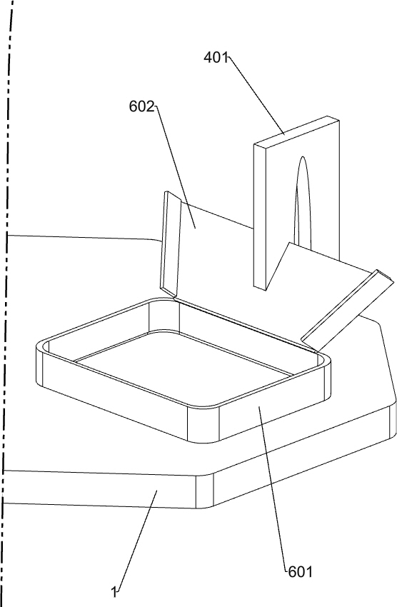
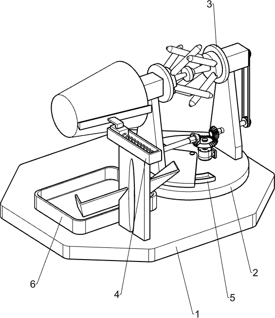
[0027] A kind of iron barrel paint evenly brushing device, such as Figure 1-9 As shown, it includes a base plate 1, a fixed plate 2, a rotating placement mechanism 3 and a brushing mechanism 4. The upper right side of the base plate 1 is provided with a fixed plate 2, and the left and right sides of the upper part of the fixed plate 2 are provided with a rotating placement mechanism 3. A brushing mechanism 4 is provided on the front side of the left part.

[0028] When people need to paint the iron barrel, first fix the iron barrel on the rotating placement mechanism 3, then start the rotating placing mechanism 3, and the brushing mechanism 4 continuously paints the iron barrel, and when the iron barrel is painted, turn off the rotating Place the mechanism 3, just take off the iron bucket, if you need to paint the iron bucket again, repeat the above steps.

[0029] The rotating placement mechanism 3 includes a first mounting plate 301, a rotating rod 302, a first bevel gear ...

Embodiment 2

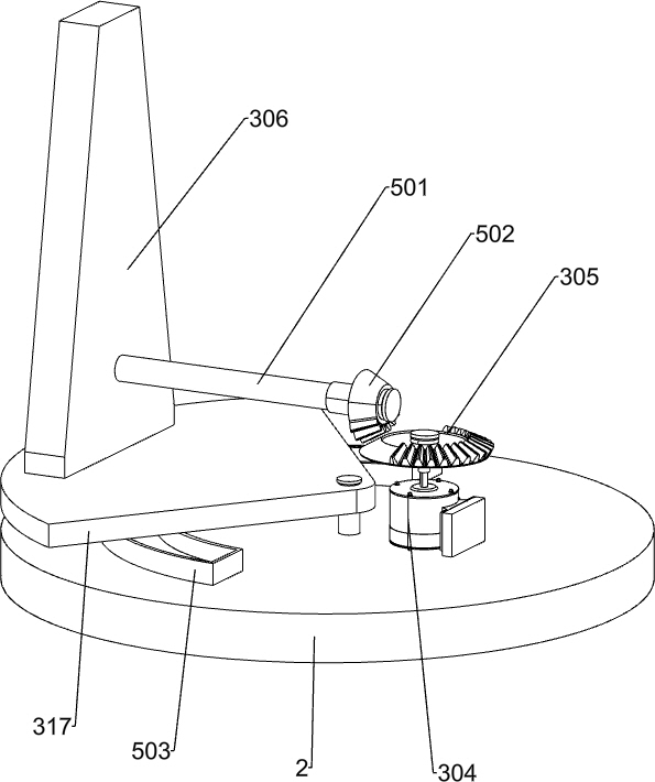
[0034] On the basis of Example 1, such as figure 1 and Figure 7-9As shown, a swing mechanism 5 is also included. The upper left side of the fixed plate 2 is provided with a swing mechanism 5. The swing mechanism 5 is in contact with the bottom of the swing plate 317. The swing mechanism 5 includes a cross bar 501, a third bevel gear 502, and an arc guide rail. 503, the second slide block 504 and the second spring 505, the second mounting plate 306 bottom () rotation type is provided with a crossbar 501, the right end of the crossbar 501 is provided with a third bevel gear 502, the third bevel gear 502 and the second bevel Gear 305 cooperates, and the left side of fixed plate 2 top is provided with arc guide rail 503, and arc guide rail 503 is positioned at pendulum plate 317 below, and the inner sliding type of arc guide rail 503 is provided with second slide block 504, and the front end of second slide block 504 and arc A second spring 505 is connected between the inner fro...


PUM


Abstract

The invention relates to a uniform brushing device, in particular to a paint uniform brushing device for an iron bucket. The invention aims to provide the paint uniform brushing device for the iron bucket being uniform in paint brushing and capable of collecting redundant paint on the iron bucket. The paint uniform brushing device for the iron bucket comprises a bottom plate, a fixed disc, rotating placement mechanisms, a uniform brushing mechanism and the like; and the fixed disc is arranged at the right side of the bottom plate, the rotating placement mechanisms are arranged at the left sideand the right side of the upper portion of the fixed disc, and the uniform brushing mechanism is arranged at the front side of the upper left portion of the bottom plate. A sponge brush on the uniform brushing mechanism makes contact with the surface of the iron bucket, and meanwhile, the iron bucket rotates continuously, so that paint can be uniformly brushed on the surface of the iron bucket; and when the sponge brush brushes the paint onto the iron bucket, scraped paint falls onto an inclined plate and a collecting box, the paint on the inclined plate freely slides into the collecting box,and people can collect the paint in the collecting box for repeated use, so that the paint is saved.

Description

technical field [0001] The invention relates to a brushing device, in particular to an iron barrel paint brushing device. Background technique [0002] An iron barrel is an iron barrel-shaped object that can be used to hold liquids and solids. It is generally cylindrical and has a bottom. [0003] Iron objects are more likely to oxidize when they are in contact with air for a long time. At the same time, because the air contains water vapor, it is easy to cause iron objects to rust. Therefore, the surface of iron buckets used by people generally needs to be painted to isolate oxygen. , to prevent the corrosion of the iron barrel, prolong the service life of the iron barrel, and also make the iron barrel more beautiful. Usually, the paint on the iron barrel is generally operated by people, so that the painted surface is relatively uneven, and the paint that slips off directly Falling to the ground is a waste. [0004] Therefore, need to research and develop a kind of brushi...

Claims


Application Information

Patent Timeline
IPC IPC(8): B05C1/02B05C11/10B05C13/02
CPCB05C1/022B05C11/10B05C11/1039B05C13/02
Inventor 刘城市
Owner 淮北开策机械科技有限公司
Why Eureka
Try Eureka