Sand screening machine for building engineering

A technology of construction engineering and sand screening machine, which is applied in the direction of screening, solid separation, and grille. filter effects, filter-friendly effects

Inactive Publication Date: 2020-11-20
苏州琦少工程科技有限公司
View PDF0 Cites 0 Cited by
  • Summary
  • Abstract
  • Description
  • Claims
  • Application Information

AI Technical Summary

Problems solved by technology

[0004] The purpose of the present invention is to solve the problem that the sand screening efficiency of the sand screening machine in the prior art is low, and the sand grains are easily blocked when they are n

Method used


Image

  • Sand screening machine for building engineering
  • Sand screening machine for building engineering
  • Sand screening machine for building engineering

Examples


Embodiment 1

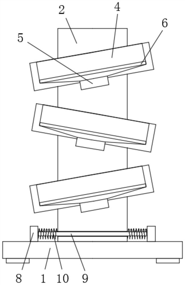
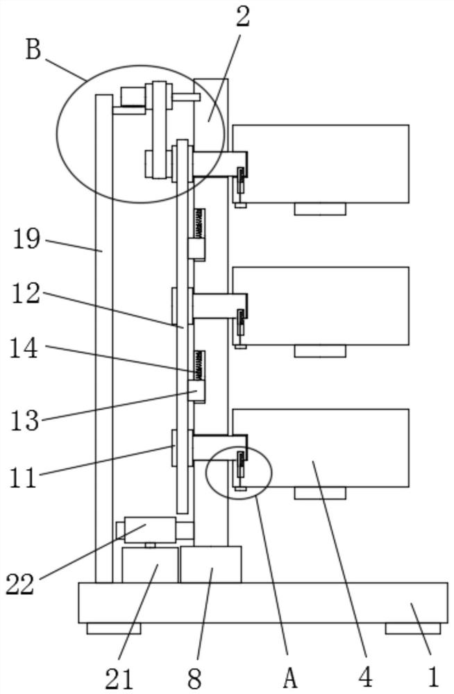
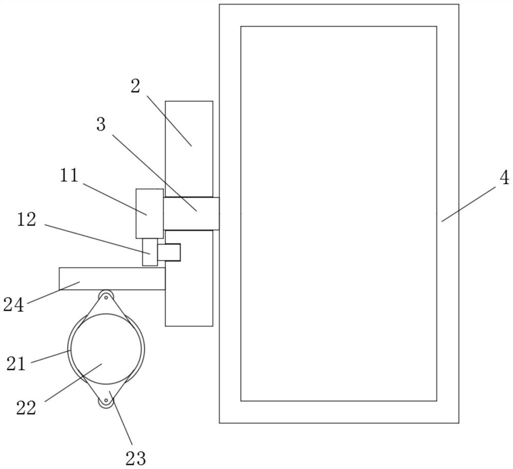
[0024] refer to Figure 1-7 , a sand screening machine for construction engineering, comprising a base plate 1, a mounting plate 2 is slidably installed on the top of the base plate 1, and three rotating holes 7 are opened on one side of the mounting plate 2, and a rotating column is installed in the three rotating holes 7 3. One end of the three rotating columns 3 is provided with a screening box 4, the tops of the three screening boxes 4 are all openings, and the inner walls of the bottom of the three screening boxes 4 are provided with feeding holes. A feeding pipe 5 is fixedly installed, a screen 6 is fixedly installed in the three screening boxes 4, a fixing hole is opened on one side of the installation plate 2, and two connecting plates 8 are fixedly installed on the top of the bottom plate 1, and the two connecting plates 8, the sides close to each other are fixedly connected with the same fixed rod 9, the fixed rod 9 is slidably connected in the corresponding fixed ho...

Embodiment 2

[0030] refer to Figure 1-7 , a sand screening machine for construction engineering, comprising a bottom plate 1, the top of the bottom plate 1 is fixed with a mounting plate 2 by bolts, one side of the mounting plate 2 is provided with three rotating holes 7, and three rotating holes 7 are installed in rotation Rotating column 3, one end of three rotating columns 3 is provided with screening box 4, and the tops of three screening boxes 4 are all openings, and the bottom inner walls of three screening boxes 4 are all provided with feeding holes, three feeding holes The feeding pipe 5 is fixed inside by bolts, and the screen 6 is fixed by bolts in the three screening boxes 4. A fixing hole is opened on one side of the mounting plate 2, and two screens are installed on the top of the bottom plate 1 by bolts. The connecting plate 8, the side of the two connecting plates 8 close to each other is fixedly connected with the same fixed rod 9 by bolts, the fixed rod 9 is slidably conn...


PUM


Abstract

The invention belongs to the field of building engineering, and particularly relates to a sand screening machine for building engineering. The sand screening machine comprises a bottom plate. A mounting plate is slidably arranged on the top of the bottom plate. One side of the mounting plate is provided with three rotating holes. Rotating columns are rotatably arranged in the three rotating holes.A screening box is arranged at one end of each of the three rotating columns. A discharging hole is formed in the inner wall of the bottom of each of the three screening boxes. Discharging pipes areeach fixedly arranged in the three discharging holes. Screens are fixedly arranged in the three screening boxes. A fixing hole is formed in one side of the mounting plate, and two connecting plates are fixedly arranged at the top of the bottom plate. The sand screening machine is reasonable in structure, convenient to operate, and high in sand screening efficiency. During sand screening, the mounting plate shakes left and right, and meanwhile, the screening box is driven to rotate back and forth, so that sand is caused to make sufficient contact with the screens, the screening effect is enhanced, and sand particles can be screened to different extents conveniently.

Description

technical field [0001] The invention relates to the technical field of construction engineering, in particular to a sand screening machine for construction engineering. Background technique [0002] Construction engineering refers to engineering entities formed through the construction of various housing buildings and their ancillary facilities and the installation activities of supporting lines, pipelines, and equipment. Projects that can form internal spaces to meet the needs of people's production, living, learning, and public activities, and various technical work such as planning, surveying, design, construction, and completion for new construction, reconstruction, or expansion of houses, buildings, and ancillary structures and facilities. The completed project entity and the installation project of its supporting lines, pipelines, and equipment also refer to the construction projects of various houses and buildings. Sand screening is an inevitable process in the constr...

Claims


Application Information

Patent Timeline
IPC IPC(8): B07B1/36B07B1/42B07B1/46
CPCB07B1/36B07B1/42B07B1/46B07B2201/04
Inventor 于宁李冲
Owner 苏州琦少工程科技有限公司
Why Eureka
Try Eureka