Circumferential water supply mechanism capable of running at high speed

A technology of water supply mechanism and high-speed rotation, which is applied to the parts of grinding machine tools, grinding machines, grinding drive devices, etc., can solve the problems of waste of water resources, failure of smooth water supply to cool mechanical equipment, and mechanical equipment unable to rotate normally.

Active Publication Date: 2020-11-20
QUANZHOU HAIENDE ELECTROMECHANICAL TECH DEV
View PDF7 Cites 0 Cited by
  • Summary
  • Abstract
  • Description
  • Claims
  • Application Information

AI Technical Summary

Problems solved by technology

[0002] When supplying water to mechanical equipment during high-speed rotation, the water inlet pipe connection is generally used to achieve the purpose of water supply, but in some mechanical equipment, circular water supply is required, and the water inlet pipes are distributed and connected to the mechanical equipment. When the mechanical equipment rotates, The water inlet pipes are rotated accordingly and twisted into hemp ropes. After a few turns, they cannot rotate due to the length of the water inlet pipes, and the mechanical equipment is blocked by the water inlet pipes and cannot rotate normally; not only cannot it rotate normally, but during high-speed operation It is impossible to smoothly supply water to cool the mechanical equipment; generally, a separate sprinkler structure is also installed outside the mechanical equipment. Circumferential water supply is carried out by diverting water through the water diversion plate. When the water diversion plate is running at high speed, under the action of centrifugal force inside the water diversion plate, the water cannot flow down with the high-speed circular operation, and the water supply mechanism cannot supply water downwards.

Method used


Image

  • Circumferential water supply mechanism capable of running at high speed
  • Circumferential water supply mechanism capable of running at high speed
  • Circumferential water supply mechanism capable of running at high speed

Examples


Embodiment Construction

[0050] In order to further explain the technical solution of the present invention, the present invention will be described in detail below through specific examples.

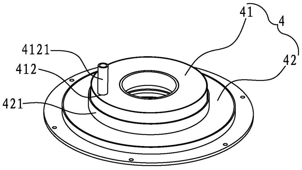
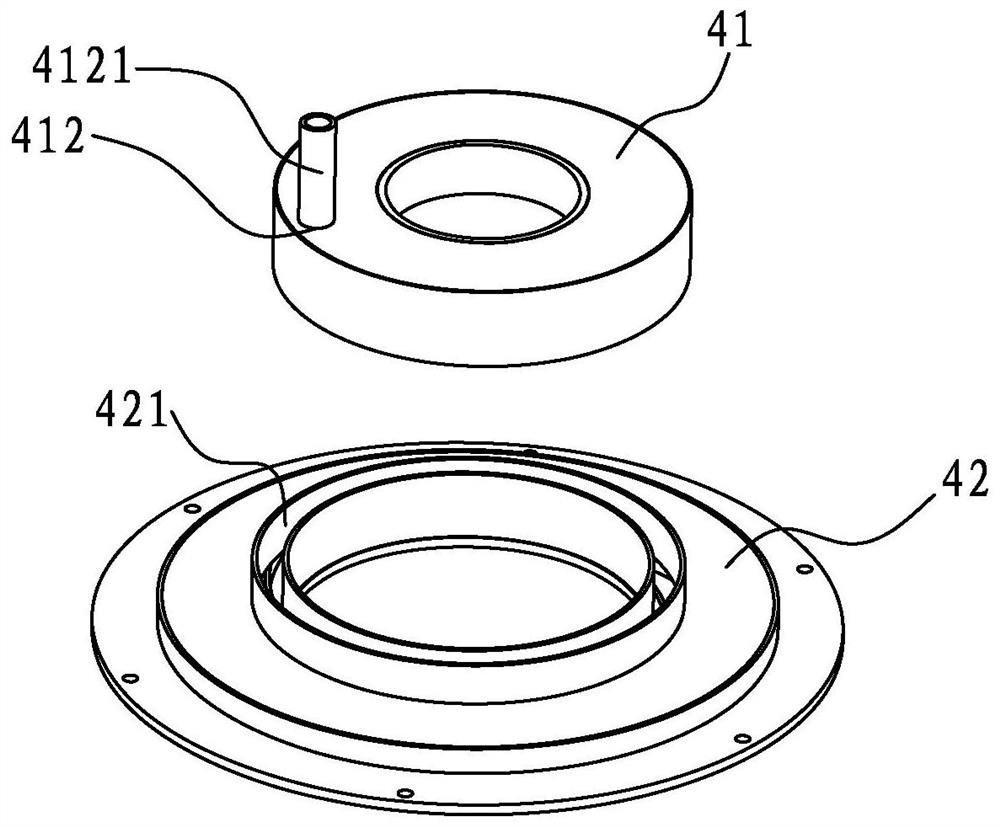
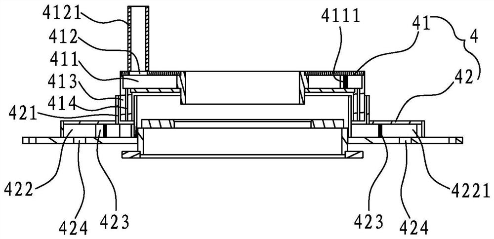
[0051] see Figure 1 to Figure 7 , the present invention discloses a circular water supply mechanism 4 capable of high-speed operation, including a lower water tray 41 and a water diversion tray 42 capable of high-speed operation; The water inlet 412 of the chamber 411, the water protruding ring 413 extending downward from the bottom wall of the water receiving chamber 411, and a plurality of circles evenly distributed on the water protruding ring 413 and communicating with the water receiving through holes 414 of the water receiving chamber 411; The water diversion plate 42 is provided with a water guide ring 421, a water diversion chamber 422, a plurality of water diversion blades 423 and a plurality of water diversion holes 424; And the lower end of the water guide ring 421 communicates with the water divid...


PUM


Abstract

The invention discloses a circumferential water supply mechanism capable of running at high speed. The circumferential water supply mechanism comprises a drainage tray and a water distribution tray capable of running at high speed; the drainage tray is provided with an annular water bearing chamber, a water inlet communicating with the water bearing chamber, a drainage convex ring extending downwards from the bottom wall of the water bearing chamber and a plurality of drainage through holes capable of being uniformly distributed on the drainage convex ring in a circumference mode and communicating with the water bearing chamber; the water distribution tray is provided with a water guide ring, a water distribution chamber, a plurality of water distribution blades and a plurality of water distribution holes; the drainage convex ring is sleeved with the water guide ring, and the lower end of the water guide ring communicates with the water distribution chamber; the plurality of water distribution blades are arranged on the bottom wall of the water distribution chamber and divide the water distribution chamber into a plurality of sub-chambers; and the plurality of water distribution holes are uniformly arranged on the bottom wall of the water distribution chamber in a circumference mode, and each sub-chamber is correspondingly provided with one water distribution hole. By means ofthe structure, the circumferential water supply mechanism can achieve the purpose of supplying water downwards through the plurality of water distribution holes distributed in a circumference mode inthe high-speed operation process, the water supply structure is simple, and the water supply is smooth.

Description

technical field [0001] The invention relates to a water supply mechanism, in particular to a circular water supply mechanism capable of high-speed operation. Background technique [0002] When supplying water to mechanical equipment during high-speed rotation, the water inlet pipe connection is generally used to achieve the purpose of water supply, but in some mechanical equipment, circular water supply is required, and the water inlet pipes are distributed and connected to the mechanical equipment. When the mechanical equipment rotates, The water inlet pipes are rotated accordingly and twisted into hemp ropes. After a few turns, they cannot rotate due to the length of the water inlet pipes, and the mechanical equipment is blocked by the water inlet pipes and cannot rotate normally; not only cannot it rotate normally, but during high-speed operation It is impossible to smoothly supply water to cool the mechanical equipment; generally, a separate sprinkler structure is also i...

Claims


Application Information

Patent Timeline
Patent Type & Authority Applications(China)
IPC IPC(8): B24B55/02B24B27/00B24B47/12
CPCB24B55/02B24B27/0076B24B47/12
Inventor 林智敏陈祖西吴江文洪培英黄嘉鸿林榕栋
Owner QUANZHOU HAIENDE ELECTROMECHANICAL TECH DEV
Why Eureka
Try Eureka