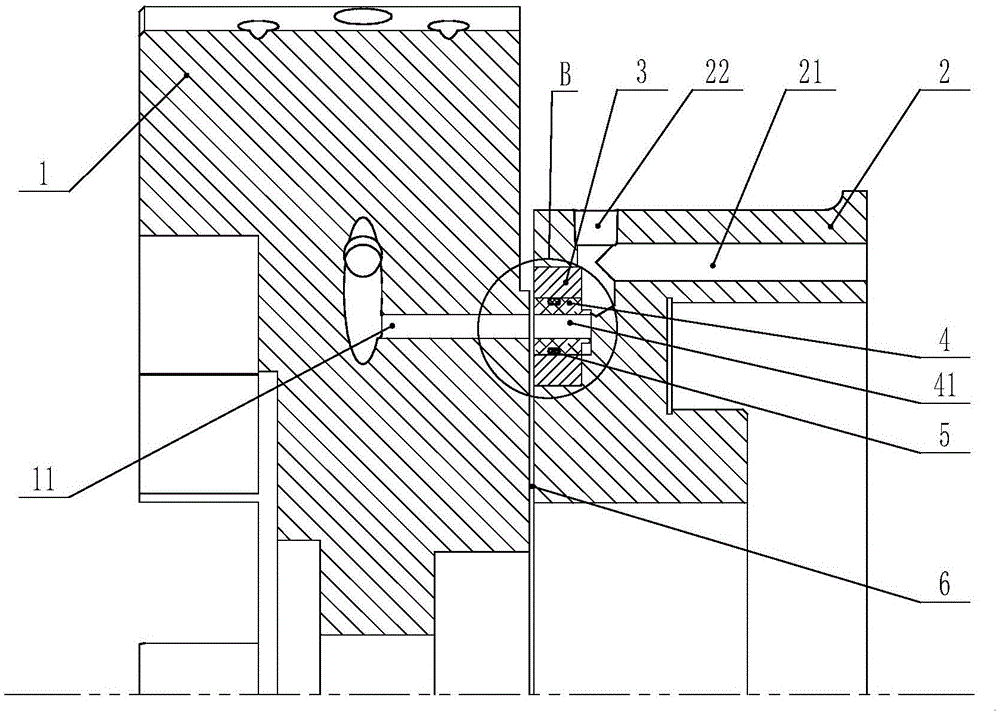
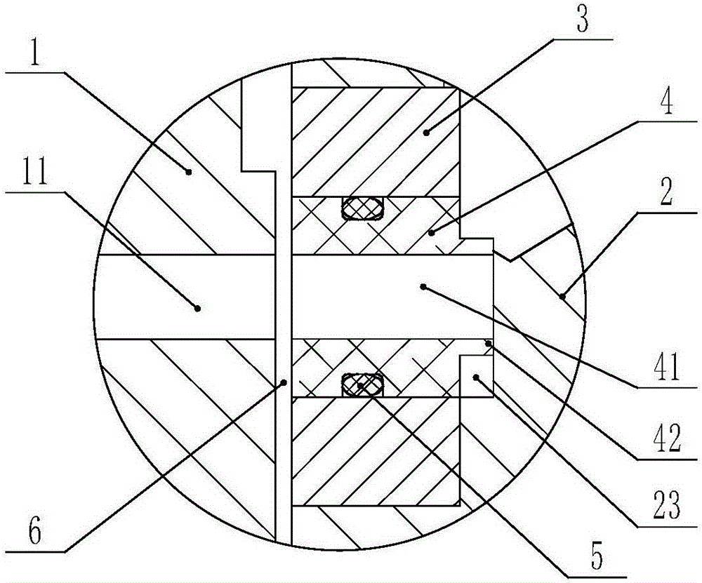
Cutter head cooling device capable of supplying liquid during rotation of cutter head

A technology of cooling device and rotating disk, which is applied in the direction of metal processing machinery parts, maintenance and safety accessories, metal processing equipment, etc., and can solve the problem that the water outlet on the tool holder cannot rotate, and the connection structure between the water inlet hole of the cutter head and the water outlet of the tool holder Complicated issues

Active Publication Date: 2016-12-07
BEIJING CTB SERVO CO LTD
View PDF10 Cites 0 Cited by
  • Summary
  • Abstract
  • Description
  • Claims
  • Application Information

AI Technical Summary

Problems solved by technology

[0005] In order to solve the above-mentioned problems in the prior art, that is, in order to solve the problem that the water outlet on the knife rest cannot be rotated and the connection structure between the water inlet hole of the knife head and the water outlet of the knife rest is complicated in the prior art, the present invention provides a The cutterhead cooling device that supplies liquid when the disk rotates, is characterized in that the cutterhead cooling device includes: a first cooling passage arranged on the cutterhead, a second cooling passage arranged on the cutter holder, and a second cooling passage arranged on the cutter head The rotary disk on the tool holder, the cutter disk is rotatably mounted on the tool holder; the rotary disk is provided with a first annular hole, and the first cooling channel can pass through the first annular hole and The second cooling passage communicates, and the rotating disk can rotate around the rotation axis of the tool holder

Method used


Image

  • Cutter head cooling device capable of supplying liquid during rotation of cutter head
  • Cutter head cooling device capable of supplying liquid during rotation of cutter head

Examples


Embodiment Construction

[0017] Preferred embodiments of the present invention are described below with reference to the accompanying drawings. Those skilled in the art should understand that these embodiments are only used to explain the technical principles of the present invention, and are not intended to limit the protection scope of the present invention. For example, although the various components in the drawings are drawn in a certain proportion, this proportional relationship is not static, and those skilled in the art can make adjustments as needed so as to adapt to specific applications.

[0018] It should be noted that, in the description of the present invention, the terms "center", "upper", "lower", "left", "right", "vertical", "horizontal", "inner", "outer" etc. The terms of the indicated direction or positional relationship are based on the direction or positional relationship shown in the drawings, which are only for the convenience of description, and do not indicate or imply that th...


PUM


Abstract

The invention belongs to the technical field of numerically-controlled machine tools and particularly provides a cutter head cooling device capable of supplying a liquid during rotation of a cutter head. The invention aims to solve the problem that in the prior art, a water outlet in a knife rest cannot rotate and the connecting structure of a water inlet hole of the cutter head and the water outlet of the knife rest is complex. The cutter head cooling device provided by the invention comprises a first cooling channel arranged on the cutter head, a second cooling channel arranged on the knife rest and a rotating disc arranged on the knife rest, wherein the cutter head is rotatably mounted on the knife rest; an annular hole is formed in the rotating disc, a connecting ring capable of sliding axially is formed in the annular hole, and the connecting ring can communicate with the first cooling channel and the second cooling channel. According to the cutter head cooling device provided by the invention, axial movement of the cutter head is replaced by axial slip of the connecting ring, so that the structure is simpler, and the rotating disc is arranged, so that the cutter head rotating to any positions can communicate with the first cooling channel and the second cooling channel to cool the cutter head.

Description

technical field [0001] The invention belongs to the field of numerical control machine tools, and specifically provides a cutter head cooling device capable of supplying liquid when the cutter head rotates. Background technique [0002] When the machine tool is processing the workpiece, the friction and cutting between the workpiece and the tool will cause a certain temperature rise to the tool, especially when the hardness of the workpiece is too large and the tool is fast-moving, it will often cause a large temperature rise of the tool and affect the tool. Life, therefore, requires cooling of the tool. At present, it is generally used to cool the cutter head and then cool the cutter head, directly cool the cutter head or simultaneously cool the cutter head and the cutter head. When cooling the cutter head, generally a water pipe is arranged on the cutter head, and the water pipe is connected to the water inlet hole of the cutter head, and then cooling liquid is passed int...

Claims


Application Information

Patent Timeline
Patent Type & Authority Applications(China)
IPC IPC(8): B23Q11/10
CPCB23Q11/10
Inventor 项久鹏郭志
Owner BEIJING CTB SERVO CO LTD
Why Eureka
Try Eureka