Pressure vessel machining method and polishing device for machining of pressure vessel

A technology of pressure vessel and grinding head, which is applied in the direction of grinding driving device, grinding/polishing safety device, spraying device, etc. It can solve the problems of single function effect, high labor intensity, and fly dust treatment, so as to improve cleaning efficiency , improve the grinding efficiency, and ensure the effect of normal operation

Inactive Publication Date: 2022-03-11
浙江九树机械有限公司
View PDF7 Cites 0 Cited by
  • Summary
  • Abstract
  • Description
  • Claims
  • Application Information

AI Technical Summary

Problems solved by technology

The invention provides a method for processing chemical pressure vessels, which can solve the following problems in the process of processing chemical pressure vessels: a. The chemical pressure vessel has a plate-shaped bending to form a cylinder, and its interface is welded and sealed by welding , so that welding slag will be produced at the welding place, that is, the welding place needs to be polished to remove the welding slag; b. In the current traditional method, most of the welding places are manually sanded and polished by a grinder, which is labor-intensive. Low work efficiency, especially for grinding the welds on the inner wall of chemical pressure vessels; c. The grinding devices currently in the market have complex structures, are expensive, and have single functions and effects, and can only be aimed at a certain specification, making their practical value not high
[0006] However, there are still problems in the above-mentioned patent: the above-mentioned grinding device does not process the flying dust and welding slag generated by grinding, which will pollute the processing environment and easily affect the human health of the staff

Method used


Image

  • Pressure vessel machining method and polishing device for machining of pressure vessel
  • Pressure vessel machining method and polishing device for machining of pressure vessel
  • Pressure vessel machining method and polishing device for machining of pressure vessel

Examples


Embodiment 1

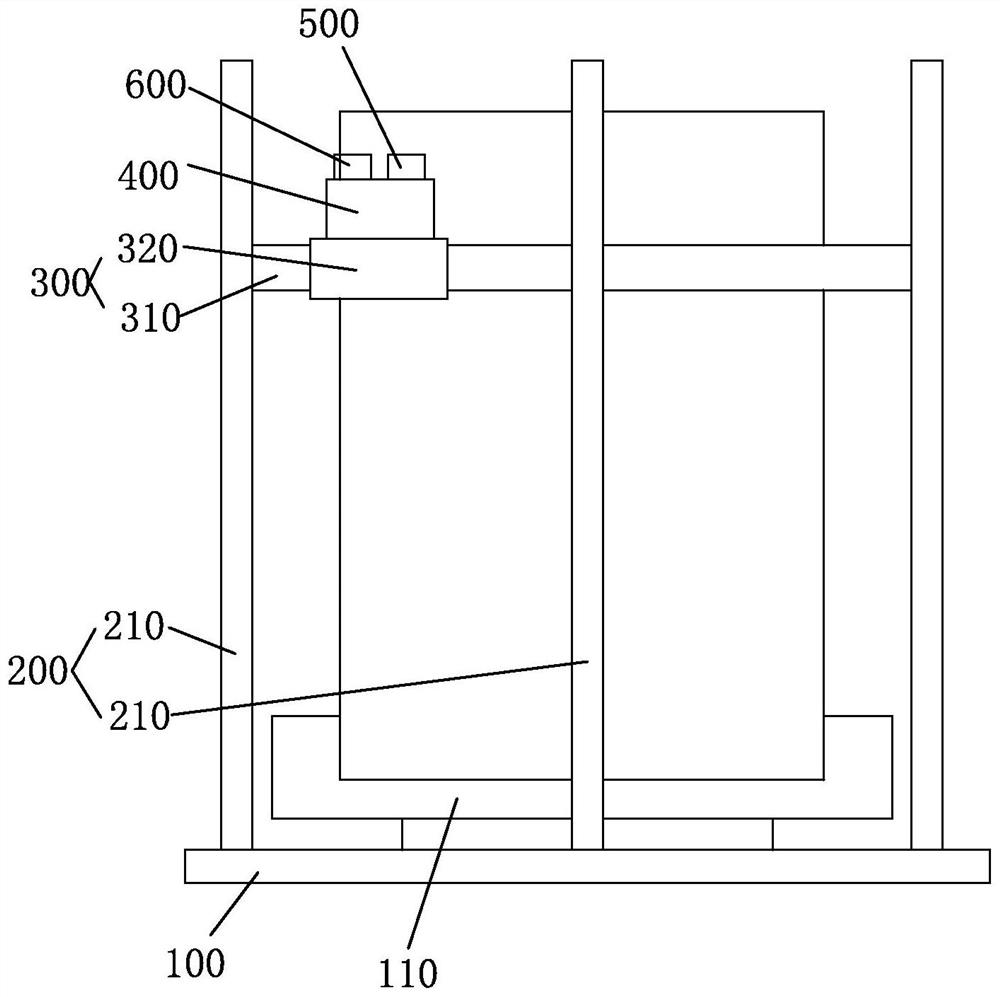
[0043] Such as figure 1 As shown, the embodiment of the present application provides a grinding device for pressure vessel processing, which includes a grinding device body. The grinding device body includes: a base 100 for placing a pressure vessel, and a rotating disc 110 is provided on the base 100 for placing the pressure vessel. On the rotating disk 110, the rotating disk 110 drives the pressure vessel to rotate; the lifting device 200 is arranged on the base 100, and the lifting device 200 includes a plurality of vertically arranged lifting rods 210 surrounding the periphery of the pressure vessel; the surrounding device 300 is arranged on the lifting On the rod 210, the surrounding device 300 includes a fixed ring 310 and a sliding block 320 arranged on the fixed ring 310, the sliding block 320 moves around the pressure vessel along the fixed ring 310, and the fixed ring 310 moves up and down along the pressure vessel through the lifting device 200 The grinding device 4...

Embodiment 2

[0046] Embodiments of the present application provide a pressure vessel processing method and a grinding device for processing thereof. In addition to the above technical features, the pressure vessel processing method and grinding device for processing of the embodiments of the present application also include the following technical features.

[0047] Such as figure 1 As shown, the grinding device 400 includes: a grinding base 100, which is installed on the sliding block 320; a driver 420, which is arranged on the grinding base 100, and the end of the driver 420 is provided with a grinding head 421, and the driver 420 drives the grinding head 421 to rotate, and the grinding head 421 is used for grinding the pressure vessel; the protective cover 430 is arranged on the outside of the grinding head 421 to prevent the dust from splashing during grinding, and one end of the protective cover 430 is connected with the grinding base 100; the collecting device 440 is arranged on one s...

Embodiment 3

[0050] Embodiments of the present application provide a pressure vessel processing method and a grinding device for processing thereof. In addition to the above technical features, the pressure vessel processing method and grinding device for processing of the embodiments of the present application also include the following technical features.

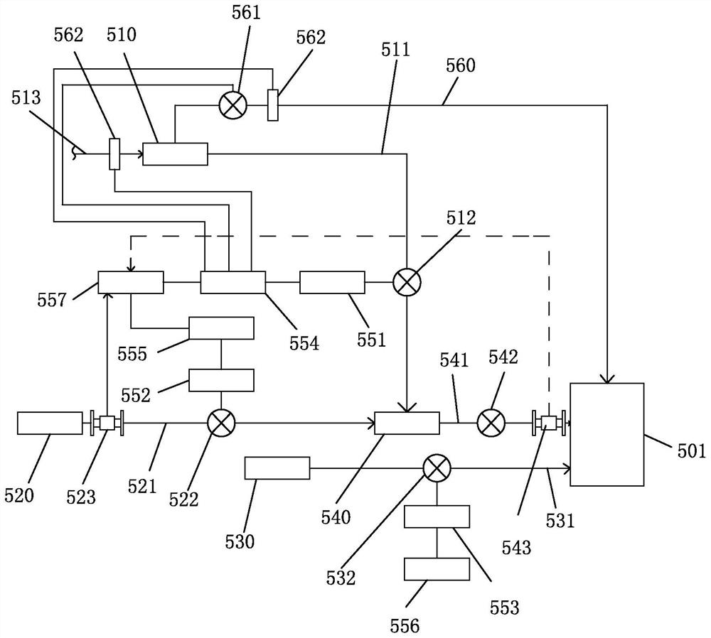
[0051] Such as figure 2As shown, the spraying device 500 includes: a sprayer 501 arranged on the protective cover 430 for spraying liquid, one end of the sprayer 501 penetrates the protective cover 430 and extends into the protective cover 430; a first liquid storage tank 510 is placed on The ground is used to store water, and the first liquid storage tank 510 is connected to the tap water pipe 513; the second liquid storage tank 520 is set on one side of the first liquid storage tank 510, and is used to store rust removal liquid; the third liquid storage tank Box 530 is arranged on one side of the second liquid storage tank 520 for ...


PUM


Abstract

The invention discloses a polishing device for pressure vessel machining, which comprises a polishing device body, the polishing device body comprises a base for placing a pressure vessel, the base is provided with a rotating disc, the pressure vessel is placed on the rotating disc, and the rotating disc drives the pressure vessel to rotate; the lifting device is arranged on the base and comprises a plurality of lifting rods which surround the periphery of the pressure container and are vertically arranged; the surrounding device is arranged on the lifting rod, the surrounding device comprises a fixing ring and a sliding block arranged on the fixing ring, the sliding block annularly moves along the fixed surrounding pressure container, and the fixing ring ascends and descends along the pressure container through the lifting device; the grinding device is arranged on the sliding block and used for grinding the pressure container, and the grinding device annularly moves along the pressure container through the surrounding device; the spraying device is arranged on the sliding block and used for spraying rust removal liquid; and the cleaning device is arranged on the spraying device and used for cleaning the spraying device.

Description

technical field [0001] The invention belongs to the technical field of pressure vessels, and in particular relates to a pressure vessel processing method and a grinding device for processing thereof. Background technique [0002] A pressure vessel refers to a closed device that contains gas or liquid and bears a certain pressure. In order to more effectively implement scientific management and safety supervision and inspection, my country's "Pressure Vessel Safety Supervision Regulations" divides pressure vessels into three categories according to working pressure, medium hazards and their role in production. [0003] A pressure vessel is a closed container that can withstand pressure. The pressure vessel has a wide range of uses, and it has an important position and role in many sectors such as industry, civil, military, and many fields of scientific research. Among them, the most used ones are in the chemical industry and the petrochemical industry, and the pressure vess...

Claims


Application Information

Patent Timeline
Patent Type & Authority Applications(China)
IPC IPC(8): B24B9/04B24B47/20B24B41/00B24B49/00B24B49/12B24B55/06B24B55/12B05B16/20
CPCB24B9/04B24B47/20B24B41/00B24B49/00B24B49/12B24B55/06B24B55/12B05B16/20
Inventor 不公告发明人
Owner 浙江九树机械有限公司
Why Eureka
Try Eureka