

Engraving device for computer hardware development
A technology of computer hardware and reclaiming mechanism, applied in workpiece clamping devices, decorative arts, embossed ornaments, etc., can solve the problems of troublesome reclaiming process, repositioning, inability to clamp and position hardware of different sizes, etc. Effects that improve accuracy and speed
- Summary
- Abstract
- Description
- Claims
- Application Information
AI Technical Summary
Problems solved by technology
Method used
Image

Examples
Embodiment 1
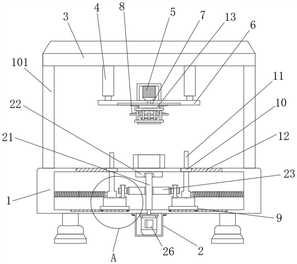
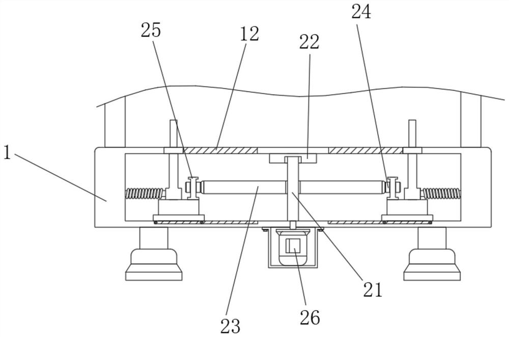
[0027] Example 1: See figure 1 , image 3 , Figure 5 , Image 6 with Figure 7 , including a workbench 1, a driving mechanism 2, a retrieving mechanism 8, a moving mechanism 9 and an engraving mechanism 13, the four corners of the top of the workbench 1 are fixedly connected with support rods 101, and the tops of the four support rods 101 are fixedly connected with a top plate 3 , the bottom of the top plate 3 and the four corners near the center are fixedly connected with telescopic cylinders 4, the bottoms of the four telescopic cylinders 4 are fixedly connected with a fixed plate 6, the center of the fixed plate 6 top is equipped with a first motor 5, and the bottom of the fixed plate 6 The central rotation is connected with a rotating disk 7, the output end of the first motor 5 is fixedly connected with the top of the rotating disk 7, the material retrieving mechanism 8 is arranged at the bottom of the rotating disk 7 and near the back side, and the engraving mechanism...
Embodiment 2
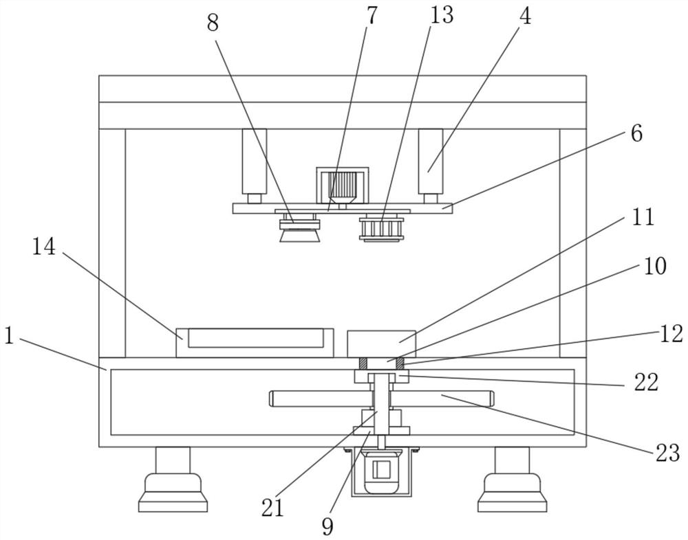
[0033] Example 2: See figure 2 with Figure 4 , the rotation angles of the first motor 5 are 0° and 180°. After the first motor 5 turns 180°, the center of the suction cup 83 in the reclaiming mechanism 8 and the center of circle of the driving wheel 23 are on the same vertical line. The top view of the driving wheel 23 The surface is elliptical, and the center of the driving wheel 23 is on the same vertical line as the center of the engraving mechanism 13. This structure is set so that after the staff limits the rotation angle of the first motor 5, when the staff needs to remove it When feeding, only need to rotate the first motor 5 to ensure that the center of the retrieving mechanism 8 and the center of the hardware on the workbench 1 are on the same vertical line, so that the retrieving mechanism 8 does not need to be positioned, and the efficiency of the retrieving process is improved. Accuracy and speed.
[0034] When using the present invention: at first the staff op...
PUM
 Abstract
Description
Claims
Application Information