
A connection structure between balance beams on a crane

A technology for connecting structures and balancing beams, applied to connecting components, mechanical equipment, load suspending elements, etc., can solve problems such as lowering the safety of the upper balancing beam, loosening nuts, and reducing the utility of the balancing beam.

Active Publication Date: 2021-04-16
SHANDONG QILIDE HEAVY IND CO LTD
View PDF5 Cites 0 Cited by
  • Summary
  • Abstract
  • Description
  • Claims
  • Application Information

AI Technical Summary

Problems solved by technology

[0003] The balance beam is an important part of the hoisting equipment, which can be used to maintain the balance of the equipment being hoisted and avoid damage to the equipment by the sling. However, the existing upper balance beam and the hook are installed by means of pins and nuts, so the After use, the nut on the pin rod is easy to loosen due to the rotation of the hook, which reduces the safety of the upper balance beam and reduces the practicality of the balance beam.

Method used


Image

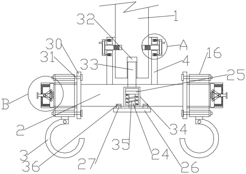
  • A connection structure between balance beams on a crane
  • A connection structure between balance beams on a crane
  • A connection structure between balance beams on a crane

Examples


Embodiment 1

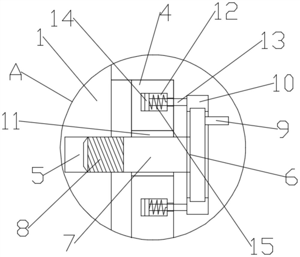
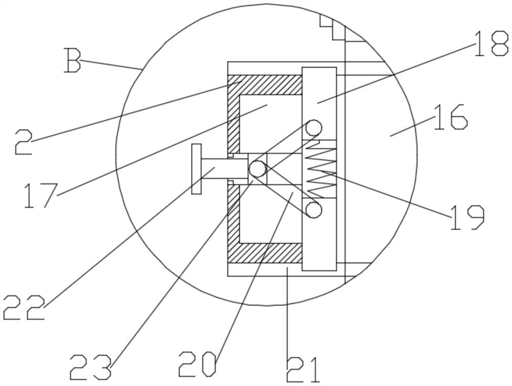
[0026] Such as Figure 1-5 As shown, in the embodiment provided by the present invention, a connection structure between balance beams on a crane includes a connecting column 1 and a balance beam main body 2, and a connection seat 4 is fixedly arranged on the upper surface of the balance beam main body 2, so that The bottom end of the connecting column 1 extends into the connecting seat 4, and the connecting column 1 extending into the connecting seat 4 is respectively connected and fixed through the first mounting assembly and the second mounting assembly; the balance beam main body 2 Supporting sliding sleeves 16 are detachably installed at both ends of the third mounting assembly, and the bottom ends of the two supporting sliding sleeves 16 are fixedly provided with a spreader 3 .

[0027] Specifically, in the embodiment provided by the present invention, the outer rings at both ends of the balance beam main body 2 are fixedly sleeved with fixed ring blocks 30, and the supp...

Embodiment 2

[0030] Such as Figure 1-5 As shown, in the embodiment provided by the present invention, a connection structure between balance beams on a crane includes a connecting column 1 and a balance beam main body 2, and a connection seat 4 is fixedly arranged on the upper surface of the balance beam main body 2, so that The bottom end of the connecting column 1 extends into the connecting seat 4, and the connecting column 1 extending into the connecting seat 4 is respectively connected and fixed through the first mounting assembly and the second mounting assembly; the balance beam main body 2 Supporting sliding sleeves 16 are detachably installed at both ends of the third mounting assembly, and the bottom ends of the two supporting sliding sleeves 16 are fixedly provided with a spreader 3 .

[0031]Specifically, in the embodiment provided by the present invention, the outer rings at both ends of the balance beam main body 2 are fixedly sleeved with fixed ring blocks 30, and the suppo...


PUM


Abstract

The embodiment of the present invention relates to the technical field of cranes, and specifically discloses a connection structure between balance beams on a crane, including a connection column and a balance beam main body; a connection seat is fixedly arranged on the upper surface of the balance beam main body, and The bottom end extends into the connecting seat, and the connecting columns extending into the connecting seat are respectively connected and fixed through the first mounting assembly and the second mounting assembly; both ends of the balance beam main body are passed through the third mounting assembly Supporting sliding sleeves are disassembled and installed, and the bottom ends of the two supporting sliding sleeves are fixedly provided with suspenders. In the connection structure of the balance beam on the crane provided in the embodiment of the present invention, the connecting column protruding into the connecting seat can be installed and fixed through the first installation assembly and the second installation assembly, and the fixing effect is good, stable and reliable; in addition , the embodiment of the present invention utilizes the third installation assembly to install the hanger with the support sliding sleeve on the balance beam main body, which has high safety and reliability.

Description

technical field [0001] The embodiment of the present invention relates to the technical field of cranes, in particular to a connection structure between balance beams on a crane. Background technique [0002] A crane refers to a multi-action hoisting machine that vertically lifts and horizontally transports heavy objects within a certain range, also known as cranes, aerial cranes, cranes, and some lifting equipment. The corresponding mechanisms for actions such as retrieving, moving, and unloading work alternately, and the development and use of cranes in the market are becoming more and more extensive. [0003] The balance beam is an important part of the hoisting equipment, which can be used to maintain the balance of the equipment being hoisted and avoid damage to the equipment by the sling. However, the existing upper balance beam and the hook are installed by means of pins and nuts, so the After use, the nut on the pin rod is easy to loosen due to the rotation of the h...

Claims


Application Information

Patent Timeline
Patent Type & Authority Patents(China)
IPC IPC(8): B66C1/10B66C13/06F16B39/284
CPCB66C1/10B66C13/06F16B39/284
Inventor 和法展和景涵和西国徐占合
Owner SHANDONG QILIDE HEAVY IND CO LTD
Learn More