T-shaped rigid framework cantilever beam bridge synchronous pushing displacement control closure method and cantilever beam bridge

A technology of displacement control and synchronous control, which is applied in the direction of bridges, bridge construction, erection/assembly of bridges, etc. It can solve the problems of poor jacking effect and inability to achieve synchronization, and achieve synchronous jacking speed, good jacking effect, and good effect Effect

Pending Publication Date: 2020-11-20
陕西路桥集团有限公司
View PDF2 Cites 1 Cited by
  • Summary
  • Abstract
  • Description
  • Claims
  • Application Information

AI Technical Summary

Problems solved by technology

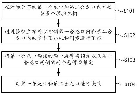
[0005] The embodiment of the present application provides a T-shaped rigid structure cantilever beam bridge synchronous jacking displacement control closing method and cantilever beam bridge to solve the technical problem that the jacking of multiple jacks cannot be synchronized and the jacking effect is poor

Method used


Image

  • T-shaped rigid framework cantilever beam bridge synchronous pushing displacement control closure method and cantilever beam bridge
  • T-shaped rigid framework cantilever beam bridge synchronous pushing displacement control closure method and cantilever beam bridge
  • T-shaped rigid framework cantilever beam bridge synchronous pushing displacement control closure method and cantilever beam bridge

Examples


Embodiment Construction

[0054] The technical solutions of the present invention will be clearly and completely described below in conjunction with the embodiments. Obviously, the described embodiments are part of the embodiments of the present invention, but not all of them. Based on the embodiments of the present invention, all other embodiments obtained by persons of ordinary skill in the art without making creative efforts belong to the protection scope of the present invention.

[0055] In the description of the present invention, it should be noted that the terms "center", "upper", "lower", "left", "right", "vertical", "horizontal", "inner", "outer" etc. The indicated orientation or positional relationship is based on the orientation or positional relationship shown in the drawings, and is only for the convenience of describing the present invention and simplifying the description, rather than indicating or implying that the referred device or element must have a specific orientation, or in a spe...


PUM


Abstract

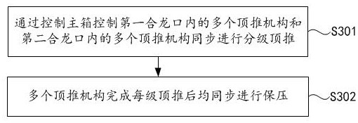
The invention discloses a T-shaped rigid framework cantilever beam bridge synchronous pushing displacement control closure method and a cantilever beam bridge, relates to the technical field of bridgeerection, and aims to solve the technical problem of poor pushing effect at present. The closure method of a cantilever beam bridge comprises the steps that a plurality of pushing mechanisms are installed in a first closure opening and a second closure opening which are symmetrically distributed; the multiple pushing mechanisms in the first closure opening and the second closure opening are synchronously controlled by controlling the main box to conduct pushing synchronously; the two cantilever beams on the two sides of the first closure opening and the two cantilever beams on the two sides of the second closure opening are locked; and the first closure opening and the second closure opening are poured. A cantilever beam bridge is closed by adopting the closing method. According to the invention, the stress of each point at the end part of each cantilever beam is consistent, and a better pushing effect is realized.

Description

technical field [0001] The invention relates to the technical field of bridge erection, in particular to a T-shaped rigid frame cantilever girder bridge synchronous pushing displacement control closing method and the cantilever girder bridge. Background technique [0002] A cantilever beam bridge is a beam bridge in which the beam body is consolidated at the top of the pier, and a simply supported beam with one or both ends freely hanging outward is used as the main load-bearing member of the upper part. During the construction process of the cantilever beam bridge, affected by factors such as the weight of the beam body, concrete shrinkage, creep and other factors, the displacement from both ends to the mid-span will occur, and secondary stress will be generated on the bridge and pier body, resulting in concrete cracking and affecting structural safety. The problem. Therefore, when the mid-span is closed, it is necessary to push and close, that is, to apply a horizontal th...

Claims


Application Information

Patent Timeline
Patent Type & Authority Applications(China)
IPC IPC(8): E01D21/10
CPCE01D21/10
Inventor 潘本金任万鹏朱其涛陈超秦杰贾旭斌
Owner 陕西路桥集团有限公司
Why Eureka
Try Eureka