Plate pushing power system

A power system and plate technology, applied in the direction of conveyor objects, transportation and packaging, etc., can solve the problems of high labor intensity and low work efficiency, and achieve the effect of reasonable structure and good pushing effect

Inactive Publication Date: 2021-03-05
铭宇科技(娄底)有限公司
View PDF6 Cites 0 Cited by
  • Summary
  • Abstract
  • Description
  • Claims
  • Application Information

AI Technical Summary

Problems solved by technology

[0002] In the existing conveying of sheet materials, most of the sheets are manually lifted to the conveyor belt one by one, and then conveyed through the conveyor belt. This method is labor-intensive and low-efficiency.

Method used


Image

  • Plate pushing power system
  • Plate pushing power system

Examples


Embodiment Construction

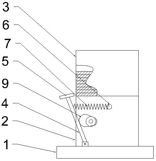
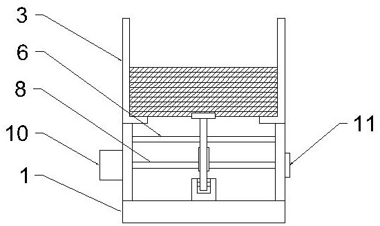
[0009]The present invention will be further described below in connection with all of the drawings, and preferred embodiments of the present invention are: see attachedfigure 1 Attachfigure 2The sheet push power system according to the present embodiment includes a rack 1, and the rack 1 is vertically fixed, and a plate plate 2 is attached to the top of the distribution side plate 2, two A plate placing zone is formed between the plate placement 3, and the top of the frame 1 between the two part plates 2 is hinged by the hinged shaft activity, and the push plate 5 is attached to the top of the swing arm 4, and the push plate 5 is located. On one end of the plate placement area, the two plates placed frames 3 of the other end of the plate placement area are opposite to the bending forming plate, and the two pieces of substrate side panel 2 are fixed to the opposite side of the plate, and the two pallets are formed between the two pallets. The arm 4 reserves the retention of the resol...


PUM


Abstract

The invention provides a plate pushing power system. The plate pushing power system comprises a rack, material distributing side plates are vertically fixed to the two sides of the top of the rack, plate containing frames are installed at the tops of the material distributing side plates, a plate containing area is formed between the two plate containing frames, and a swing arm is movably hinged to the position, between the two material distributing side plates, of the top of the rack through a hinge shaft; and a push plate is installed at the top of the swing arm, a cross beam is movably fixed between the two material distributing side plates, a tension spring is connected between the cross beam and the upper portion of the swing arm, a power shaft is movably installed between the two material distributing side plates and below the cross beam, and a cam is installed in the middle of the power shaft. After the scheme is adopted, the structure is reasonable, and the pushing effect is good.

Description

Technical field[0001]The present invention relates to the field of sheet materials, in particular, refers to a sheet push power system.Background technique[0002]The existing plate material is delivered, mostly by manually put a plate onto the conveyor belt, and then transported through the conveyor belt, using this manual labor intensity, low work efficiency.Inventive content[0003]It is an object of the present invention to overcome the shortcomings of the prior art, providing a sheet push power system that is reasonable, and a good push effect is good.[0004]In order to achieve the above object, the technical solution provided by the present invention is: a sheet push power system, which includes a rack, vertical fixation side plates on both sides of the top of the rack, and a sheet plate is mounted on top of the distribution side plate. The frame is formed between the two sheet places, and the top of the frame between the two sheets, the top of the frame is hinged by the hinge shaf...

Claims


Application Information

Patent Timeline
IPC IPC(8): B65G47/82
CPCB65G47/82
Inventor 廖东阳潘拥中向海燕
Owner 铭宇科技(娄底)有限公司
Why Eureka
Try Eureka