A Harmonic Drive Reduction Mechanism
A deceleration mechanism and harmonic transmission technology, which is applied in the transmission device, transmission device parts, mechanical equipment, etc., can solve the problems of difficult replacement, wear of the outer ring gear of the flexible gear, rotation misalignment of the flexible gear and the rigid gear, etc., and achieve convenience The effect of replacement
- Summary
- Abstract
- Description
- Claims
- Application Information
AI Technical Summary
Problems solved by technology
Method used
Image

Examples
Embodiment 1
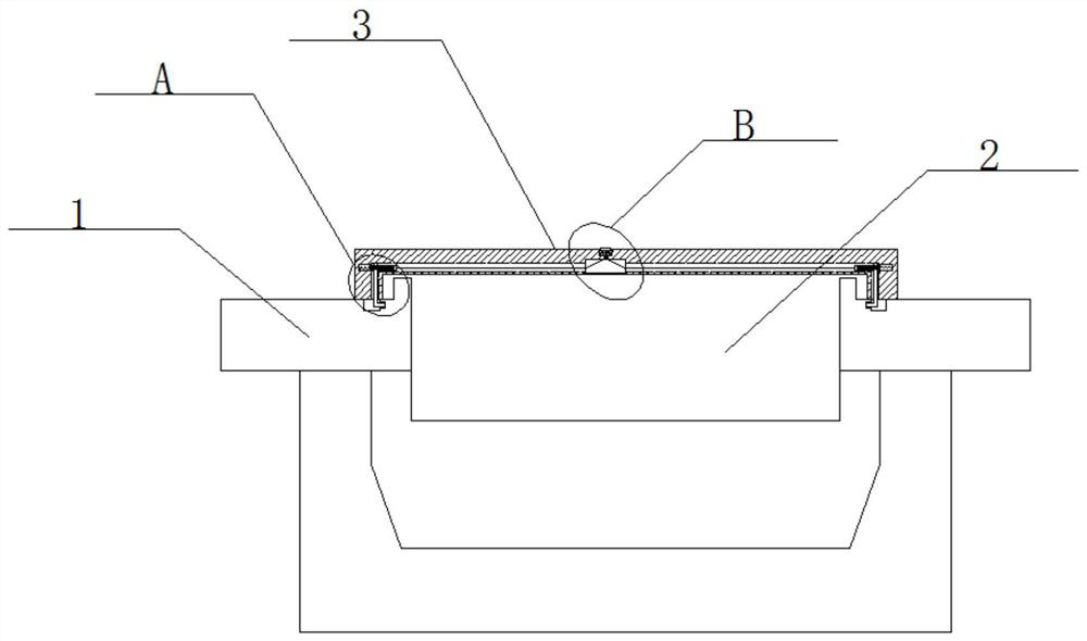
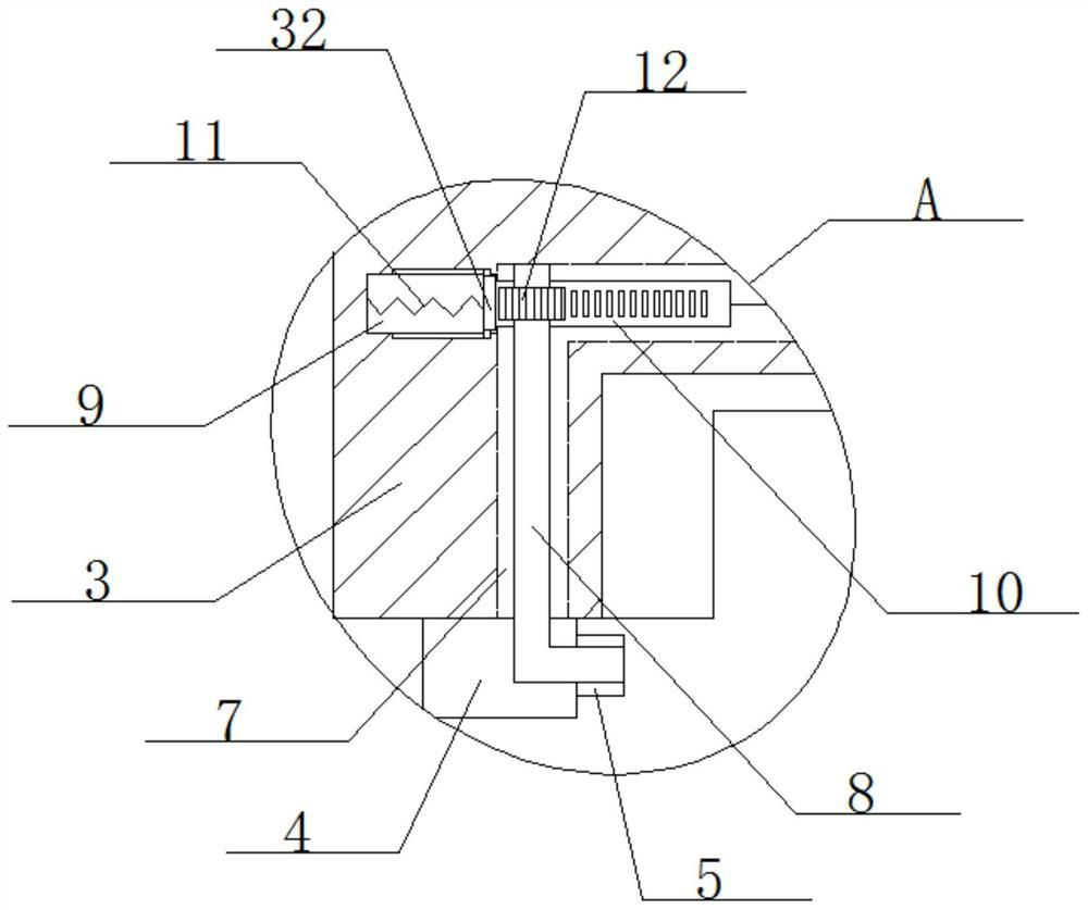
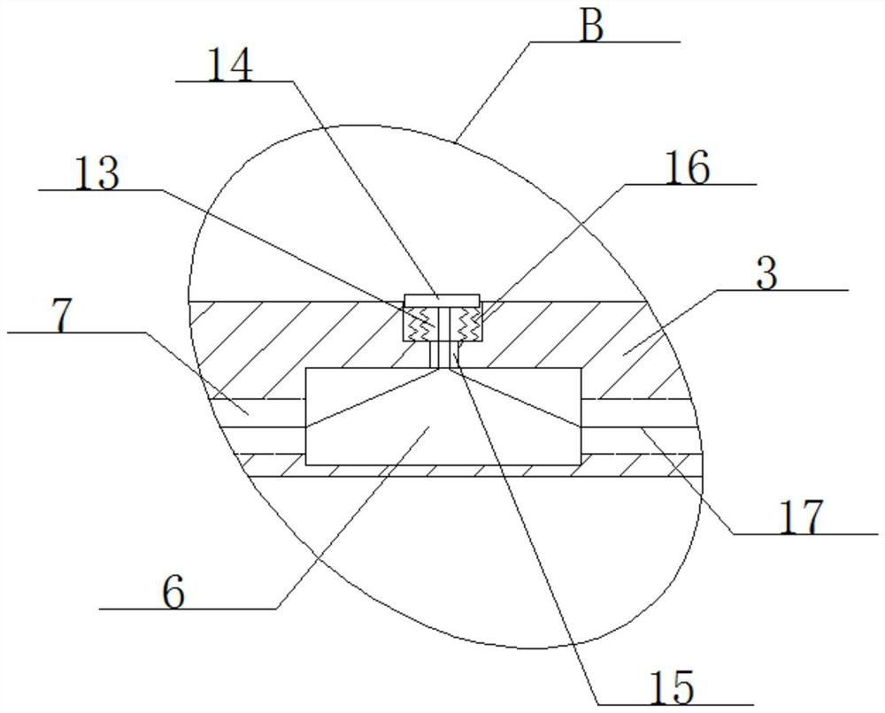
[0025] refer to Figure 1-5 , a harmonic drive reduction mechanism, including a rigid gear 1, a flexible gear 2 and an anti-displacement cover 3, two grooves 4 are respectively opened on the rigid gear 1, and the inner walls of the two grooves 4 are close to each other. An arc-shaped groove 5 is provided, and a cavity 6 is provided inside the anti-displacement cover 3, and an L-shaped hole 7 is provided on the inner wall of both sides of the cavity 6, and an L-shaped hole 7 is rotated on the inner wall of the top side of the L-shaped hole 7. Rod 8, and the bottom end of the L-shaped rod 8 extends into the arc-shaped groove 5, the L-shaped rod 8 is compatible with the arc-shaped groove 5, and two L-shaped holes 7 are provided with long grooves on the inner wall of the side away from each other 9, and a movable block 32 is slidably installed in the long groove 9, and a rack 10 is fixedly installed on the side where the two movable blocks 32 are close to each other, and a movable...
Embodiment 2
[0032] refer to Figure 1-5, a harmonic drive reduction mechanism, including a rigid gear 1, a flexible gear 2 and an anti-displacement cover 3, two grooves 4 are respectively opened on the rigid gear 1, and the inner walls of the two grooves 4 are close to each other. An arc-shaped groove 5 is provided, and a cavity 6 is provided inside the anti-displacement cover 3, and an L-shaped hole 7 is provided on the inner wall of both sides of the cavity 6, and an L-shaped hole 7 is rotated on the inner wall of the top side of the L-shaped hole 7. Rod 8, and the bottom end of the L-shaped rod 8 extends into the arc-shaped groove 5, the L-shaped rod 8 is compatible with the arc-shaped groove 5, and two L-shaped holes 7 are provided with long grooves on the inner wall of the side away from each other 9, and a movable block 32 is slidably installed in the long groove 9, and a rack 10 is fixedly installed on the side where the two movable blocks 32 are close to each other, and a movable ...
Embodiment 3
[0039] refer to Figure 1-5 , a harmonic drive reduction mechanism, including a rigid gear 1, a flexible gear 2 and an anti-displacement cover 3, two grooves 4 are respectively opened on the rigid gear 1, and the inner walls of the two grooves 4 are close to each other. An arc-shaped groove 5 is provided, and a cavity 6 is provided inside the anti-displacement cover 3, and an L-shaped hole 7 is provided on the inner wall of both sides of the cavity 6, and an L-shaped hole 7 is rotated on the inner wall of the top side of the L-shaped hole 7. Rod 8, and the bottom end of the L-shaped rod 8 extends into the arc-shaped groove 5, the L-shaped rod 8 is compatible with the arc-shaped groove 5, and two L-shaped holes 7 are provided with long grooves on the inner wall of the side away from each other 9, and a movable block 32 is slidably installed in the long groove 9, and a rack 10 is fixedly installed on the side where the two movable blocks 32 are close to each other, and a movable...
PUM
 Abstract
Description
Claims
Application Information