Pressing auxiliary punching device based on automobile carbon fiber part machining

A stamping device and carbon fiber technology, applied in the field of parts stamping and forming, can solve the problems of secondary stamping of carbon fiber parts, smooth surface of parts, and auxiliary pressing of parts, etc.

Active Publication Date: 2020-06-19
湖北衍驰科技有限责任公司
View PDF8 Cites 1 Cited by
  • Summary
  • Abstract
  • Description
  • Claims
  • Application Information

AI Technical Summary

Problems solved by technology

[0005] In order to solve the above technical problems, the present invention provides a compacting auxiliary stamping device based on the processing of automobile carbon fiber parts, to solve the problem that when the existing auxiliary stamping device for automobile carbon fiber parts is used, it usually only performs preliminary stamping without repressing. structure, it is impossible to perform

Method used


Image

  • Pressing auxiliary punching device based on automobile carbon fiber part machining
  • Pressing auxiliary punching device based on automobile carbon fiber part machining
  • Pressing auxiliary punching device based on automobile carbon fiber part machining

Examples


Embodiment

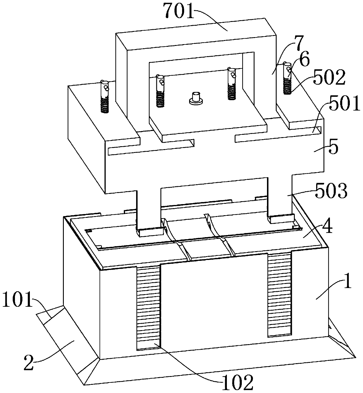
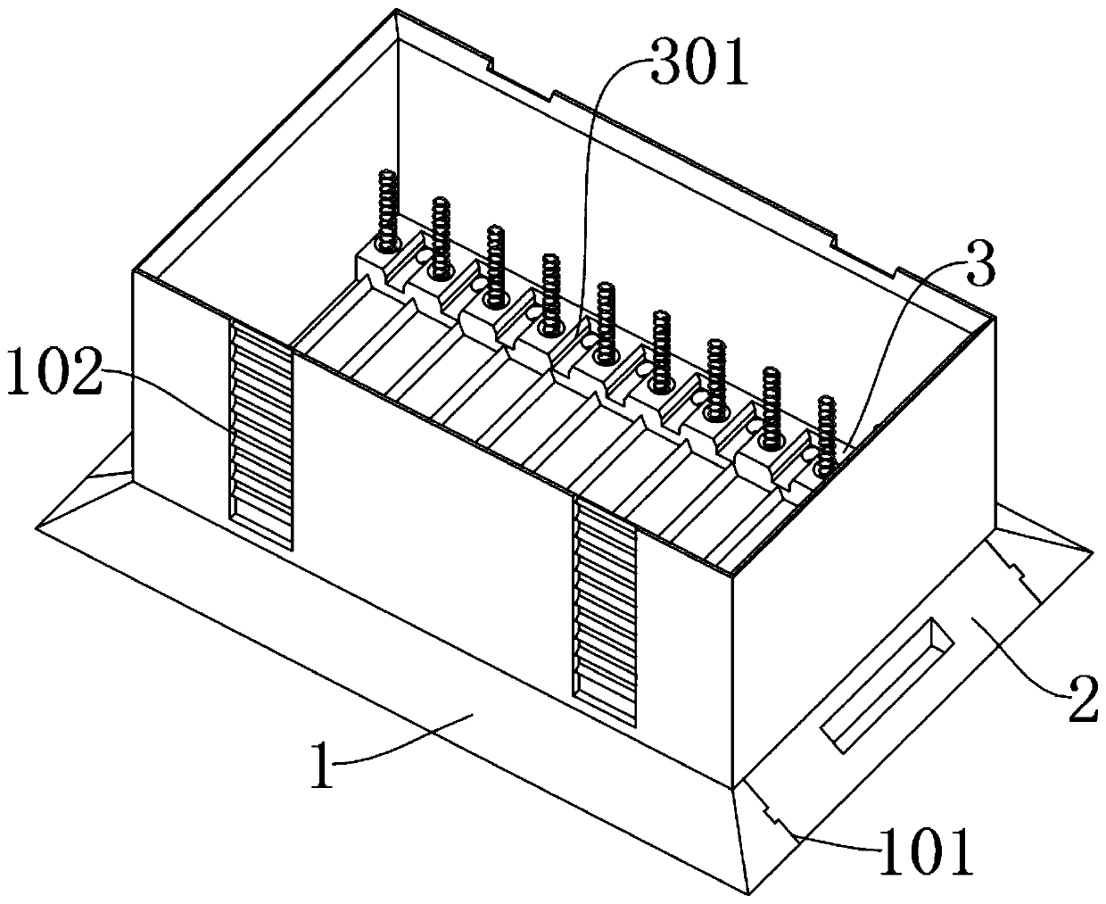
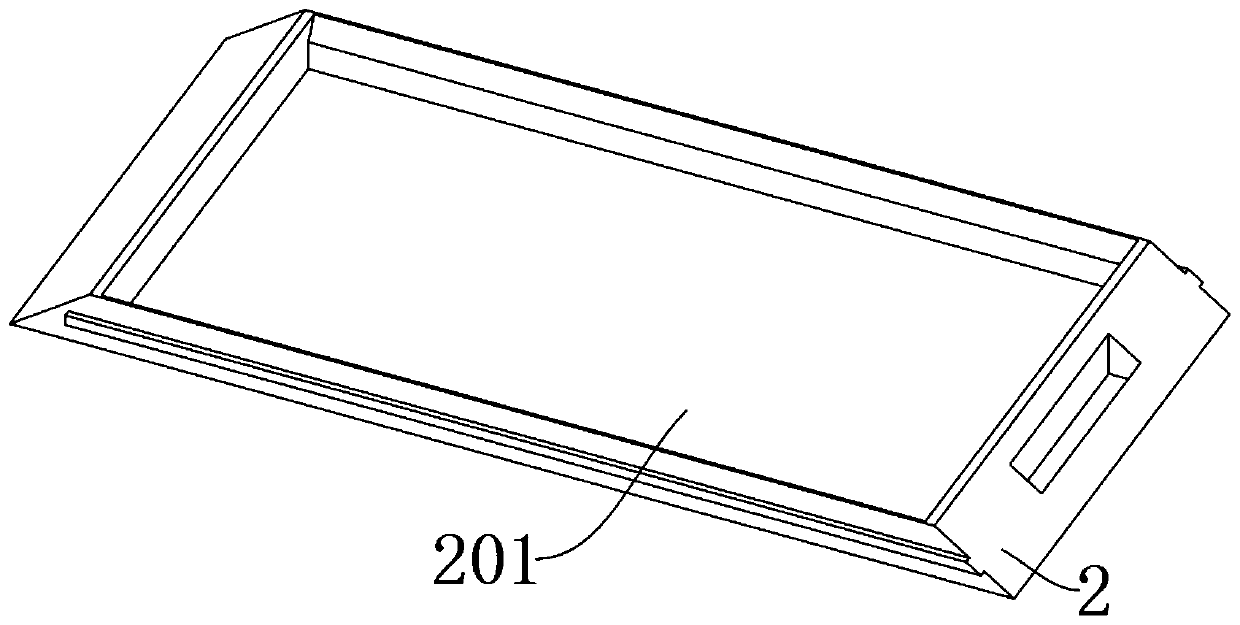
[0030] as attached figure 1 to attach Figure 8 Shown:

[0031] The invention provides a pressing auxiliary stamping device based on the processing of automobile carbon fiber parts, including: a main body 1, a bottom part 2, a limiting part 3, a moving part 4, a top part 5, a rotating part 6 and a stamping head 7; the main body 1 is a rectangular structure, and both sides of the bottom of the main body 1 are inclined structures, and the limit groove 102 is used to contact the fixed block inside the adjustment plate 503 through the stopper inside, so that the stoppers at different positions The fixed block can be fixed at different heights, so that the top piece 5 can be fixed at an appropriate height to press and stamp the carbon fiber; the bottom piece 2 is installed inside the installation groove 101 at the bottom of the main body 1, and the guides on both sides of the bottom piece 2 The block is embedded in the inside of the embedding groove, and the guide blocks on both ...


PUM


Abstract

The invention provides a pressing auxiliary punching device based on automobile carbon fiber part machining. The pressing auxiliary punching device comprises a body, a bottom part, limiting parts, a moving part, an ejecting part, rotating parts and a punching head. The body is of a rectangular structure, and the two sides of the bottom of the body are of inclined structures. The bottom part is installed in an installation groove in the bottom of the body, and guide blocks on the two sides of the bottom part are embedded and installed in embedded grooves. The limiting parts are installed at theinner bottom end of the body in a fixed connection manner, and the limiting parts are used for being arranged at the inner bottom end of the body so that when the ejecting part makes contact with themoving part to conduct primary punching forming on carbon fiber parts, the ejecting part can be used for downwards ejecting the moving part continuously. Thus, the bottom of the moving part can makecontact with the limiting parts again, the carbon fiber parts can be punched and pressed again, after the parts are formed, the surfaces can be more smooth, and insertion grooves are used for clampingblocks at the bottom of the moving part to be embedded.

Description

technical field [0001] The invention belongs to the technical field of part stamping and forming, and more specifically relates to a pressing auxiliary stamping device based on the processing of automobile carbon fiber parts. Background technique [0002] When the car carbon fiber tail is produced, it is usually necessary to use pressing auxiliary tools, so that the tail can be more standard and beautiful when it is formed. Due to the light weight of carbon fiber, carbon fiber tail is widely used in racing cars and super sports cars. [0003] For example, the application number: CN201910753616.9 relates to a carbon fiber composite stamping mold, including an upper mold assembly, and a lower mold assembly matching the upper mold assembly, wherein the upper mold assembly includes: The upper die base, the punch assembly located at the bottom of the upper die base, and the backing plate located between the upper die base and the punch assembly; the lower die assembly includes: t...

Claims


Application Information

Patent Timeline
IPC IPC(8): B29C43/02B29C43/32
CPCB29C43/02B29C43/32
Inventor 王世祥
Owner 湖北衍驰科技有限责任公司
Why Eureka
Try Eureka