Automobile generator rotor size measuring device

A technology of automobile generator and measuring device, applied in the field of machinery, can solve problems such as affecting efficiency, complicated operation, etc., and achieve the effects of improving measurement accuracy, avoiding interference, and having a simple structure

Active Publication Date: 2020-11-20
TAIZHOU EASTERN CNC EQUIP CO LTD
View PDF8 Cites 3 Cited by
  • Summary
  • Abstract
  • Description
  • Claims
  • Application Information

AI Technical Summary

Problems solved by technology

[0003] In the existing measurement process, the above-mentioned dimensions are generally measured sequentially manually, and the operation of the entire measurement process is relatively cumbersome, which seriously affects the efficiency

Method used


Image

  • Automobile generator rotor size measuring device
  • Automobile generator rotor size measuring device
  • Automobile generator rotor size measuring device

Examples


Embodiment 1

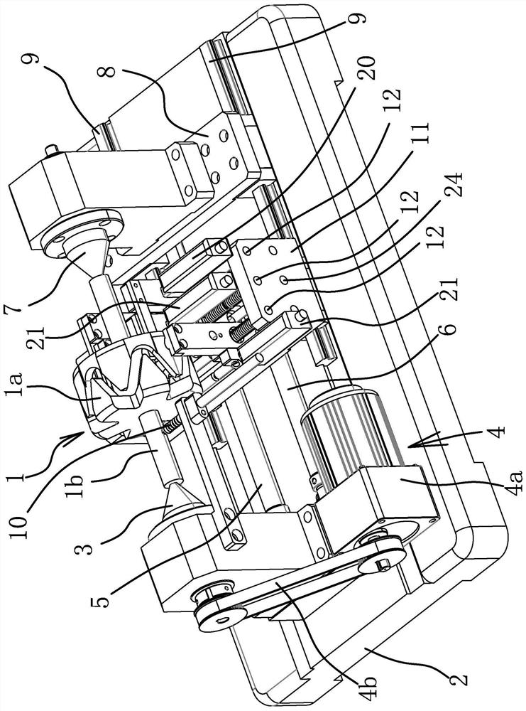
[0034] Such as figure 1 As shown, the automobile generator rotor includes an annular claw pole 1a and a shaft body 1b penetrating the claw pole 1a. The device for measuring the rotor size of an automobile generator includes a base 2, a top 3 arranged on the base 2, and a driving source 4 for driving the top 3 to rotate.

[0035] Wherein, the top 3 is rotatably connected with the base 2, and in this embodiment, the rod of the top 3 is rotatably connected with the base 2 through multiple sets of bearings. The driving source 4 includes a motor 4a fixed on the base 2 and a driving mechanism for connecting the motor 4a and the center 3. In this embodiment, the motor 4a is arranged on one side of the center-1, and the driving mechanism includes a driving wheel fixed on the main shaft of the motor 4a and a driven wheel fixed on the end of the center-1, and the driving wheel and the driven wheel are synchronized With 4b connection. Naturally, the driving source 4 can also be a motor 4a...

Embodiment 2

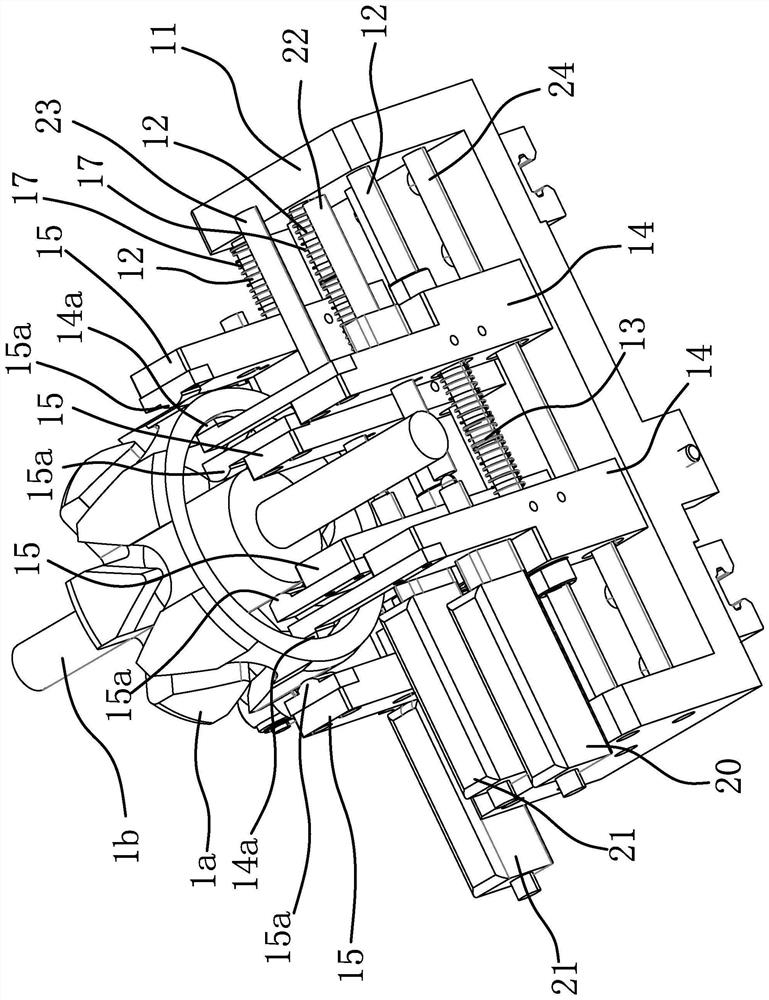
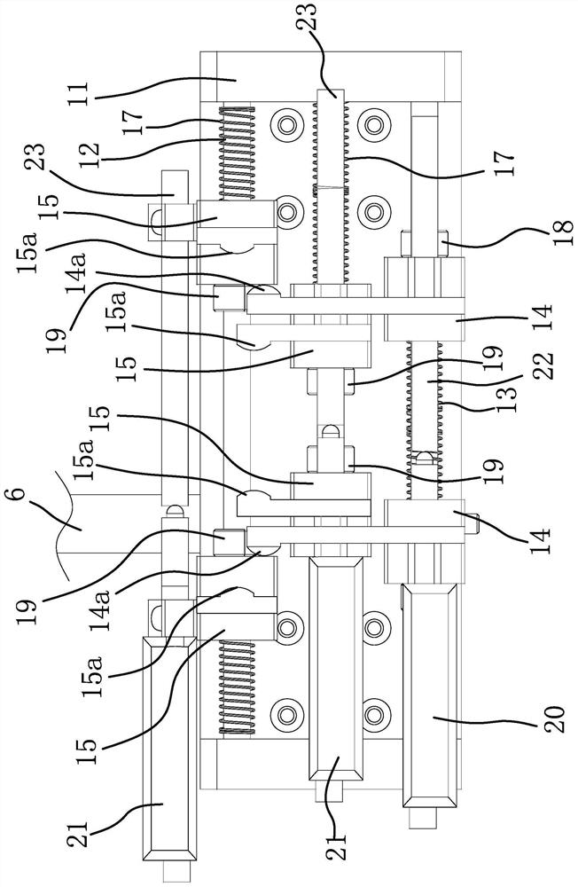
[0052] The structure and principle of the second embodiment are basically the same as those of the first embodiment. The difference lies in: the limiting structure one includes the ring body one fixed on the corresponding guide rod 12 and the convex ring one and two formed on the guide rod 12 The base block 14 is located between the convex ring one and the ring body one, and under the action of the spring 13, the two base blocks 14 press against the ring body one and the convex ring one respectively.

Embodiment 3

[0054] The structure and principle of the third embodiment are basically the same as those of the first embodiment. The difference lies in: the limiting structure one includes two convex rings two formed on the corresponding guide rod 12, and the two convex rings two are located in a pair of base blocks 15 Under the action of the spring assembly, the two base blocks 15 respectively press against the two convex rings.


PUM


Abstract

The invention provides an automobile generator rotor size measuring device, and belongs to the technical field of machinery. In the present invention, a rotor comprises a claw pole and a shaft body; the measuring device comprises a base, a first tip arranged on the base and a driving source used for driving the first tip to rotate, the base is further provided with a first driving part, a second driving part, a second tip and a pedestal, the second tip is coaxial with the first tip, the second tip is rotatably connected with the pedestal, and the first driving part is used for driving the pedestal to reciprocate along the axis of the second tip; an inspection mechanism for simultaneously measuring the inner diameter and the outer diameter of the claw pole and the diameter of the shaft bodyat the claw pole is arranged between the first tip and the second tip, and the second driving part is used for driving the inspection mechanism to translate back and forth along the axis of the second tip; a telescopic displacement sensor used for measuring radial runout of the end of the shaft body is horizontally arranged between the first tip and the inspection mechanism, and the axis of thetelescopic displacement sensor is perpendicular to the axis of the second tip. The device is high in efficiency.

Description

Technical field [0001] The invention belongs to the technical field of machinery, and relates to a size measuring device, in particular to a size measuring device of an automobile generator rotor. Background technique [0002] The existing automobile generator rotor generally includes a ring-shaped claw pole and a shaft penetrating the claw pole. After the rotor is processed, it is generally necessary to measure the diameter of the end of the rotor, the inner diameter and outer diameter of the claw pole, and the diameter of the part of the shaft inside the claw pole (that is, the middle part of the shaft). [0003] In the existing measurement process, the above-mentioned dimensions are generally measured manually in sequence, and the entire measurement process is cumbersome to operate, which seriously affects efficiency. Summary of the invention [0004] The purpose of the present invention is to solve the above-mentioned problems in the prior art and propose a high-efficiency meas...

Claims


Application Information

Patent Timeline
Patent Type & Authority Applications(China)
IPC IPC(8): G01B21/10G01B21/14G01B13/02G01B7/02
CPCG01B21/10G01B21/14G01B13/02G01B7/02
Inventor 赵玲刚
Owner TAIZHOU EASTERN CNC EQUIP CO LTD
Why Eureka
Try Eureka