
Workpiece clamping device used in hardware stainless steel production process

A production process, stainless steel technology, applied in the direction of metal processing machinery parts, metal processing, metal processing equipment, etc., can solve the problems of insufficient clamping, square workpiece damage, waste of time, etc., to achieve convenient clamping installation, convenient observation, The effect of reducing the number of steps measured

Inactive Publication Date: 2019-12-13
江门市新会区司前贸易中心有限公司
View PDF0 Cites 2 Cited by
  • Summary
  • Abstract
  • Description
  • Claims
  • Application Information

AI Technical Summary

Problems solved by technology

[0004] Aiming at the deficiencies of the prior art, the present invention provides a workpiece clamping device in the production process of hardware and stainless steel, which has the advantages of stability and convenient measurement, and solves the problem that the device can clamp circular and square workpieces, but the common The shape clamp clamps its interior, which is convenient for clamping round workpieces, and when clamping square workpieces, its circular clamps are likely to cause damage to the four corners of square workpieces, and when facing irregular square devices , the clamping is not stable enough, and it is common to measure the width of the workpiece during use. It is common to measure it with a measuring device, which makes the operation cumbersome and wastes time.

Method used


Image

  • Workpiece clamping device used in hardware stainless steel production process
  • Workpiece clamping device used in hardware stainless steel production process

Examples


Embodiment Construction

[0017] The following will clearly and completely describe the technical solutions in the embodiments of the present invention with reference to the accompanying drawings in the embodiments of the present invention. Obviously, the described embodiments are only some, not all, embodiments of the present invention. Based on the embodiments of the present invention, all other embodiments obtained by persons of ordinary skill in the art without making creative efforts belong to the protection scope of the present invention.

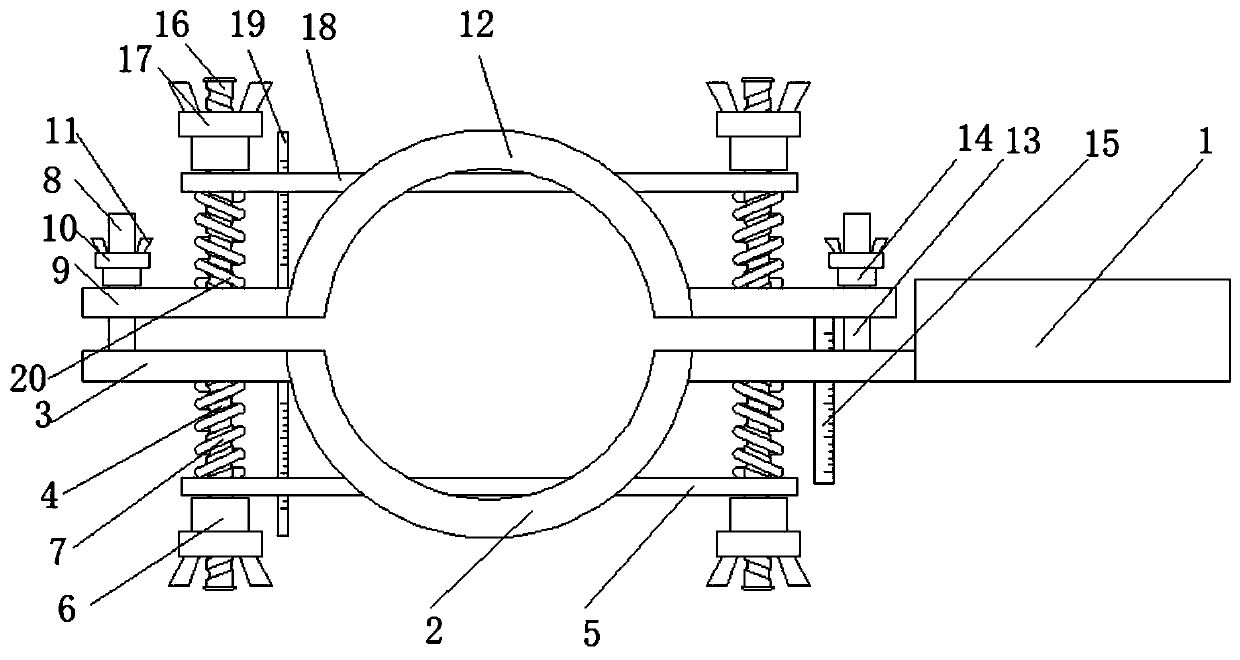
[0018] see Figure 1-2 , a workpiece clamping device in the production process of hardware and stainless steel, comprising a handrail 1, the lower part of one side of the handrail 1 is fixedly connected with a clamp bottom circular splint 2, and one side of the clamp bottom circular splint 2 is fixedly connected with a clamp Tightener side support plate-3, the middle part of the lower part of clamper side support plate-3 is fixedly connected with a spiral supp...


PUM


Abstract

The invention relates to the technical field of hardware production equipment and discloses a workpiece clamping device used in the hardware stainless steel production process. The workpiece clampingdevice comprises a handrail, and a clamping device bottom round clamping plate is fixedly connected with the lower portion of one side of the handrail. By means of the workpiece clamping device used in the hardware stainless steel production process, the scale marks of a second straight ruler and a device with the lower portion the same with the second straight ruler are observed, the moving distance of a second square clamping device and a first square clamping device is observed, the distance between the top end of the lower portion of a clamping device top round clamping plate and the upperend of the interior of the clamping device bottom round clamping plate is observed at the position of a first straight ruler, during use, the scale marks on the first straight ruler are calculated, and the workpiece clamping distance is measured by subtracting the distance between the second straight ruler and the device with the lower portion having the same position with the second straight ruler. Due to the fact that the first straight ruler and the second straight ruler are arranged, the workpiece clamping distance can be conveniently observed, measuring steps are reduced during use, useis more convenient, practicability is improved, and the workpiece clamping device is more convenient and faster.

Description

technical field [0001] The invention relates to the technical field of hardware production equipment, in particular to a workpiece clamping device in the production process of hardware and stainless steel. Background technique [0002] In the production process of stainless steel, stainless steel pipes with different rules need to be clamped. The device can clamp round and square workpieces, but the common way is to clamp the inside of them with a circular clamp, which is convenient. For clamping round workpieces, when clamping square workpieces, the circular clamp is easy to cause damage to the four corners of the square workpiece, and when facing irregular square devices, its clamping is not stable enough, so its hardware The workpiece clamping device in the stainless steel production process is improved. [0003] During use, its device clamps round and square workpieces, but it is common to clamp its interior with a circular clamp, which is convenient for clamping round ...

Claims


Application Information

Patent Timeline
Patent Type & Authority Applications(China)
IPC IPC(8): B23Q7/04B23Q17/20
CPCB23Q7/043B23Q17/20
Inventor 梁日能
Owner 江门市新会区司前贸易中心有限公司
Learn More