

Laser range finder calibration method for three-dimensional measurement
A technology of a laser rangefinder and a calibration method, which is applied to measurement devices, instruments, etc., can solve the problems of difficult imaging and processing of laser spots.
- Summary
- Abstract
- Description
- Claims
- Application Information
AI Technical Summary
Problems solved by technology
Method used
Image


Examples
Embodiment Construction
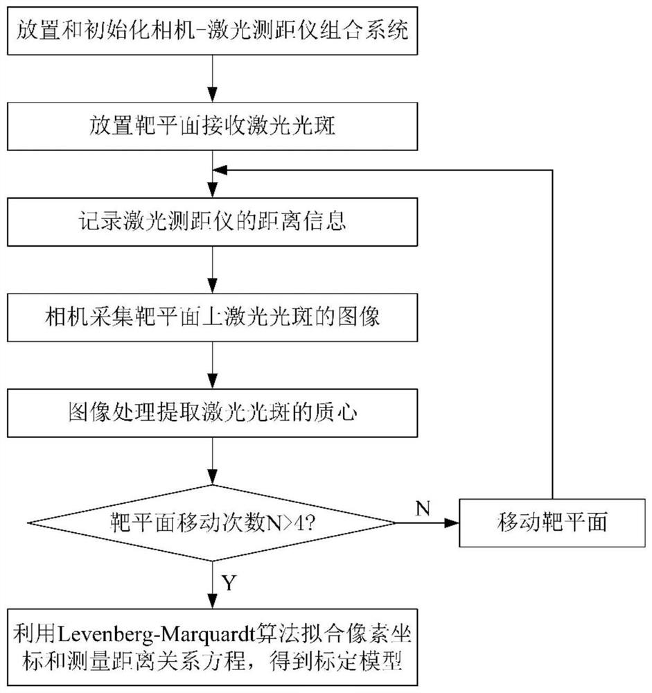
[0028] The invention provides a calibration method for a laser rangefinder that can be used for three-dimensional measurement in harsh environments. The present invention will be further described below in conjunction with the accompanying drawings and specific embodiments.
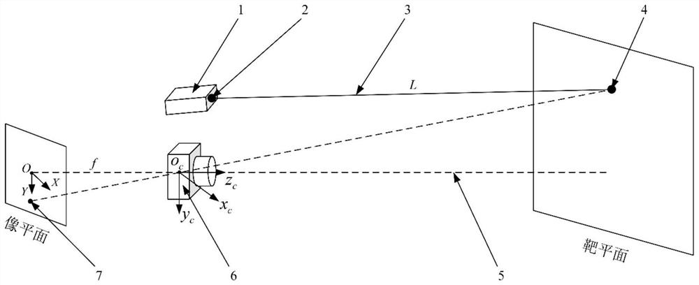
[0029] (1) Install the camera and laser rangefinder on the same rotating platform of the two-dimensional turntable to form a camera-laser rangefinder combination system, and place it in a good measurement environment, and adjust the laser axis and camera of the laser rangefinder during installation The optical axis is approximately parallel to ensure that the laser spot is located in the field of view of the camera. After the installation is completed, the relative position of the camera and the laser rangefinder should remain fixed;
[0030] (2) Place the laser spot receiving target plane in front of the camera-laser rangefinder combination system built in step (1), so that the laser spot of the laser ra...
PUM
 Abstract
Description
Claims
Application Information