Three-dimensional laser radar based on liquid crystal on silicon and scanning method

A silicon-based liquid crystal and three-dimensional laser technology, which is applied in the directions of optics, nonlinear optics, electromagnetic wave re-radiation, etc.

Active Publication Date: 2020-10-23
SHENZHEN KYLE OPTICS TECH CO LTD
View PDF6 Cites 2 Cited by
  • Summary
  • Abstract
  • Description
  • Claims
  • Application Information

AI Technical Summary

Problems solved by technology

[0005] The technical problem to be solved by the present invention is that the driving source technology of optical active phased array technology is still immature, the cost is very high, and does not meet the requirements of industrial application; the anti-vibration performanc...

Method used


Image

  • Three-dimensional laser radar based on liquid crystal on silicon and scanning method
  • Three-dimensional laser radar based on liquid crystal on silicon and scanning method
  • Three-dimensional laser radar based on liquid crystal on silicon and scanning method

Examples


Embodiment 1

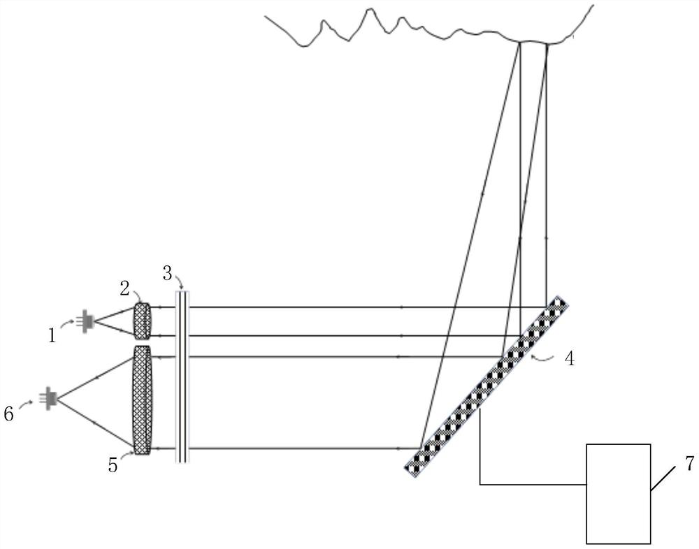
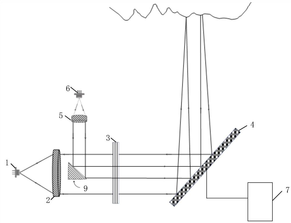
[0053] Embodiment 1 of the present invention provides a three-dimensional laser radar based on liquid crystal on silicon, such as figure 1 and figure 2 As shown, it includes a transmitting light source 1, a transmitting optical component 2, a polarizing device 3, a silicon-based liquid crystal 4, a receiving optical component 5, a receiving detector 6 and a control device 7, specifically:

[0054] Both the emitting light source 1 and the receiving detector 6 are arranged in parallel (such as figure 1 structure shown) or coaxial way (such as figure 2 The structure shown) is arranged on one side of the polarizing device 3, wherein the emitting optical assembly 2 is located on the emitting optical path between the emitting light source 1 and the polarizing device 3; the receiving optical assembly 5 is located on the The receiving optical path between the receiving detector 6 and the polarizing device;

[0055] The silicon-based liquid crystal 4 is arranged on the other side ...

Embodiment 2

[0068] The embodiment of the present invention also introduces a new type of phase control algorithm to control the energy of the beam rotation in the required +1 level switching direction, so as to improve the energy of the laser detection beam effectively controlled by the laser radar. The embodiment of the present invention can be implemented alone as a test optimization process, or can be implemented in combination with the technical solution of Embodiment 1. Next, the embodiment 2 of the present invention will be described as the matching test optimization process of the embodiment 1 solution.

[0069]Before completing the receive detector 6 setup, as Figure 10 As shown, first set the CCD8 at the position where the detector 6 was originally set, and the CCD8 is used to detect the energy value of each received light spot, so as to transmit the corresponding result to the processor, and the processor is based on the received received light. The energy value of the spot ge...

Embodiment 3

[0082] The embodiment of the present invention proposes a three-dimensional laser radar scanning method based on silicon-based liquid crystals, which is implemented as a scanning method under the same inventive concept as that of Embodiment 1 and Embodiment 2. The related content of the method function can also be applied to the embodiment of the present invention, therefore, it will not be repeated in the description of the associated technical features.

[0083] In the embodiment of the present invention, the control voltage of each picture element is used as the optical signal reflection device in the transmitting optical path and the receiving optical path, which has an independent adjustment function, such as Figure 12 As shown, the methods include:

[0084] In step 201, a plurality of picture elements in the region corresponding to the emitting light signal of the liquid crystal on silicon are controlled, so that the emitting light signal is reflected to the target obje...


PUM


Abstract

The invention relates to the technical field of laser radars, and provides a three-dimensional laser radar based on a liquid crystal on silicon and a scanning method. A transmitting light source and areceiving detector are arranged on one side of a polarization device in a common optical axis mode. A transmitting optical assembly is located on a transmitting optical path between the transmittinglight source and the polarization device. A receiving optical assembly is positioned on a receiving optical path between the receiving detector and the polarization device. A liquid crystal on siliconis arranged on the other side of the polarization device and used for reflecting the emitted light polarized by the polarization device to a to-be-measured target object at a first specified angle and reflecting the received light reflected back from the to-be-measured target object at a second specified angle. According to the invention, different phase distributions are downloaded by using theliquid crystal on silicon to realize two-dimensional measurement of the length and width dimensions of the to-be-measured target, the height dimension of the to-be-measured target is measured throughlaser beams of two polarization states, so that the three-dimensional measurement of the to-be-measured target is realized.

Description

【Technical field】 [0001] The invention relates to the technical field of laser radar, in particular to a silicon-based liquid crystal-based three-dimensional laser radar and a scanning method. 【Background technique】 [0002] Lidar has long been used in surveying and mapping, military, and navigation. With the rise of auto-driving cars, Lidar has received more widespread attention. LiDAR determines the distance, shape, state and other indicators of the measurement target through the time difference between emitting laser light and receiving reflected laser light. LiDAR mainly has two scanning methods, namely mechanical scanning and non-mechanical scanning. The mechanical scanning method has the advantages of mature technology, simple structure and low cost, and has become the mainstream beam scanning method of current lidar. However, there are also a series of problems in the mechanical scanning method. The size is large, the scanning speed is slow, and the moving parts are...

Claims


Application Information

Patent Timeline
IPC IPC(8): G01S7/481G01S17/88G02F1/133G02F1/1362
CPCG01S7/4817G01S17/88G02F1/13306G02F1/136277
Inventor 张石李亚锋鲁佶陈俊麟
Owner SHENZHEN KYLE OPTICS TECH CO LTD
Why Eureka
Try Eureka