Coupling lens capable of realizing incident light and return light detection

A coupling lens and lens technology, applied in the field of coupling lenses, can solve problems such as easy assembly tolerance, and achieve the effect of simple and reliable structure

Inactive Publication Date: 2020-11-20
SHENZHEN DULE PRECISION MFG
View PDF8 Cites 1 Cited by
  • Summary
  • Abstract
  • Description
  • Claims
  • Application Information

AI Technical Summary

Problems solved by technology

[0004] To sum up, the purpose of the present invention is to solve the existing technical deficiencies such as the structure of the coupling lens in the optical module coupling or the optical fiber temperature sensor coupling module to realize the backlight monitoring, which is easy to produce assembly tolerances, etc. Coupling lens for light detection

Method used


Image

  • Coupling lens capable of realizing incident light and return light detection
  • Coupling lens capable of realizing incident light and return light detection
  • Coupling lens capable of realizing incident light and return light detection

Examples


Embodiment 1

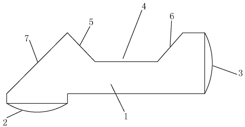
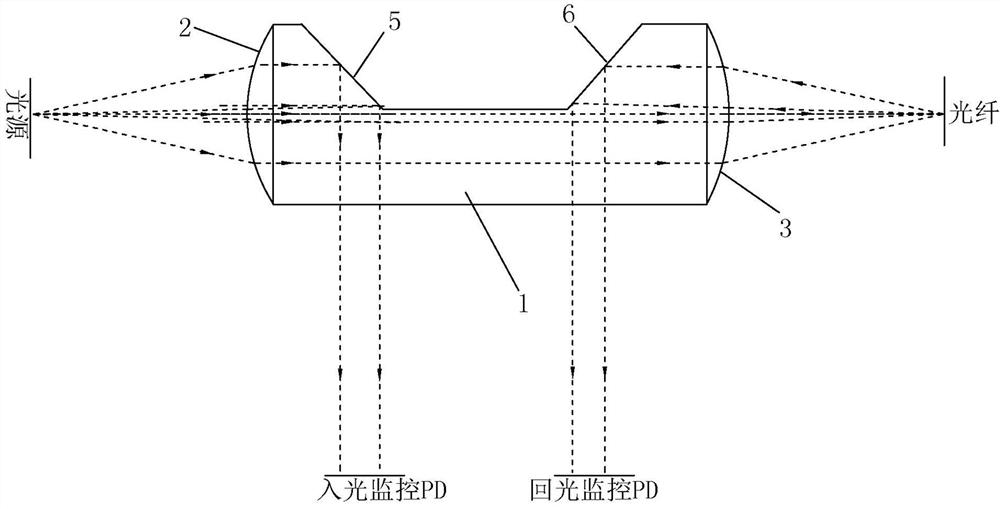
[0018] refer to figure 1 and figure 2 As shown in , the present invention discloses a coupling lens capable of detecting incident light and returning light, including a lens body 1, on which is provided a light incident collimator lens 2 corresponding to light incident from a light source, and used for The light-emitting focusing lens 3 that focuses the incoming light of the incoming light-collimating lens 2 and emits light; the lens body 1 is provided with a trapezoidal groove structure 4 that is recessed into the optical path; the trapezoidal groove structure 4 includes a The part of the incident light entered by the lens 2 is totally reflected and emitted to the second total reflection surface 5 on the incident light monitoring PD, and the part of the returned light returned by the outgoing light focusing lens 3 is totally reflected and emitted to the third total reflection surface 5 on the returned light monitoring PD. The reflection surface 6; the second total reflectio...

Embodiment 2

[0026] refer to image 3 As shown in , the difference between this embodiment and embodiment 1 is that the first total reflection surface 7 is cancelled, and other structural principles are the same as embodiment 1, that is, specifically the incident light collimating lens 2 and the light exit focusing lens 3 Located on opposite sides of the lens body 1, the axis of the incident light collimating lens 2 and the axis of the outgoing light focusing lens 3 are on the same straight line; part of the incident light of the incident light collimating lens 2 is directed to the second total reflection surface 5, The rest of the light exits directly onto the focusing lens 3 ; part of the returned light from the exiting focusing lens 3 directly strikes the third total reflection surface 6 .


PUM


Abstract

The invention discloses a coupling lens capable of realizing incident light and return light detection, and relates to the technical field of coupling lenses in optical module coupling or optical fiber temperature sensor coupling modules. The technical defects that an existing structure for achieving backlight monitoring of the coupling lens in an optical module coupling or optical fiber temperature sensor coupling module is prone to generating assembly tolerance and the like are overcome. The coupling lens comprises a lens main body, and the lens main body is provided with an incident light collimating lens and an emergent light focusing lens; the lens main body is provided with a trapezoidal groove structure which is recessed into a light path; and the trapezoidal groove structure comprises a second total reflection surface for carrying out total reflection on a part of incident light entering the incident light collimating lens and emitting the light to the incident light monitoringPD, and a third total reflection surface for carrying out total reflection on a part of return light returned by the emergent light focusing lens and emitting the light to the return light monitoringPD, wherein the second total reflection surface and the third total reflection surface form a 90-degree included angle. An energy light splitting film does not need to be attached, and light signalsof incident light and returned light can be synchronously monitored; extra assembly matching is not needed, and the structure is simple and reliable.

Description

technical field [0001] The invention relates to the technical field of coupling lenses in optical module coupling or optical fiber temperature sensor coupling modules. Background technique [0002] The coupling lens of the existing optical module coupling or optical fiber temperature sensor coupling module generally does not have light incident monitoring and return light monitoring, and in the specific application process, due to other factors such as ambient temperature or aging, the output power of the light source will fluctuate In the prior art, since the output power of the light source cannot be monitored at any time, real-time adjustment and adaptation cannot be achieved. [0003] The currently published Chinese patent application number: 201410759532.3, titled: Optical components with backlight monitoring for high-speed transmission, although the output optical power can be monitored, but the technical solution is: need to attach energy to the lens substrate Spectr...

Claims


Application Information

Patent Timeline
Patent Type & Authority Applications(China)
IPC IPC(8): G02B6/42G02B6/32
CPCG02B6/32G02B6/4206G02B6/4225G02B6/4286
Inventor 谢衍琛
Owner SHENZHEN DULE PRECISION MFG
Why Eureka
Try Eureka