Pipe surface grinding processing device
A technology for processing devices and pipes, which is applied in the direction of grinding workpiece supports, metal processing equipment, grinding machines, etc., and can solve problems such as threats to the health of operators, large injuries, and manned grinding machines
- Summary
- Abstract
- Description
- Claims
- Application Information
AI Technical Summary
Problems solved by technology
Method used
Image
Examples
specific Embodiment approach 1
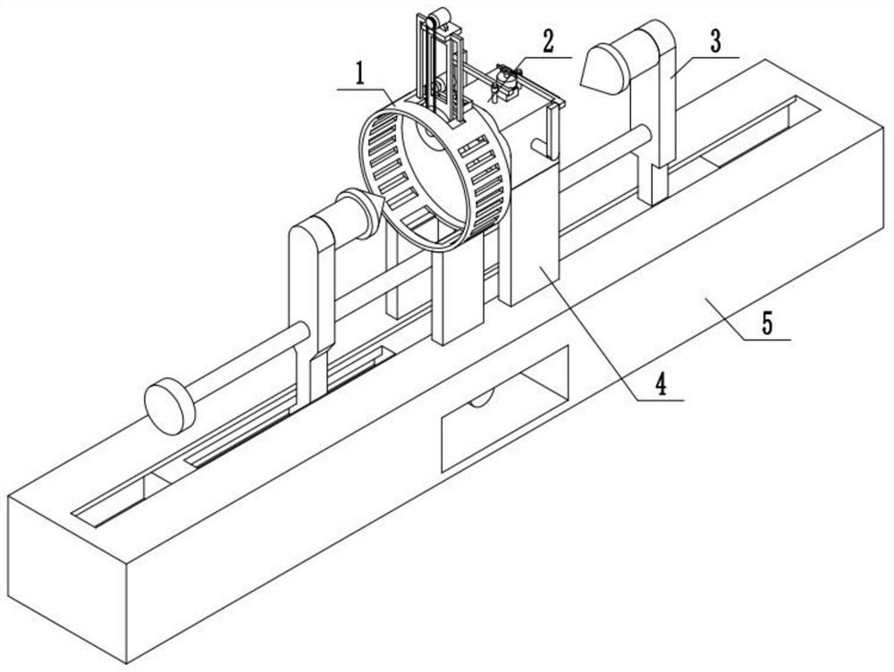
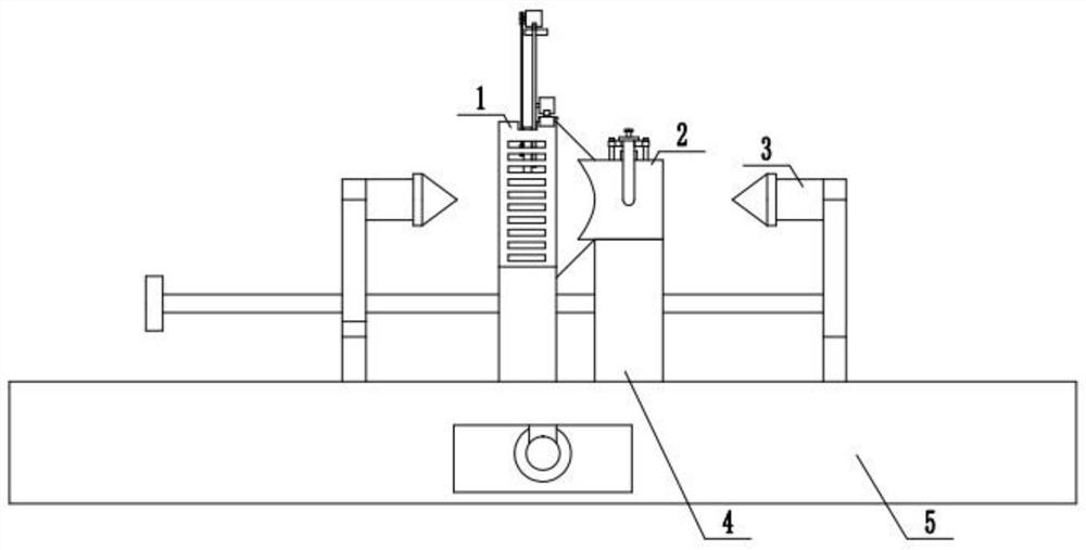
[0031] Combine below figure 1 , 2 To explain this embodiment, a pipe surface grinding and processing device includes a grinding structure 1, a supporting grinding structure 2, a steel pipe fixing structure 3, a fixed supporting plate 4, and a fixed base 5. The grinding structure 1 is fixedly installed on the supporting grinding structure 2, the fixed structure 3 is slidably installed on the fixed base 5, the fixed supporting plate 4 is fixedly installed on the fixed base 5, the fixed supporting plate 4 is fixedly installed with a supporting grinding structure 2, and the grinding structure 1 is fixedly installed on the fixed base 5.
specific Embodiment approach 2
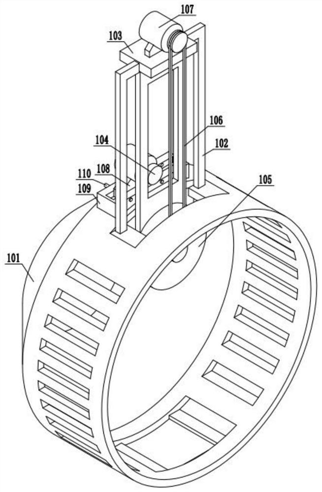
[0033] Combine below image 3 , 4 5 and 6 illustrate this embodiment. This embodiment further explains the first embodiment. The grinding structure 1 includes an outer casing 101, a guide frame 102, a driving frame 103, a power motor A104, a grinding wheel 105, a transmission belt 106, The power motor B107, the motor sliding frame 108, the sliding base 109, the fixing pin 110, the outer casing 101 is provided with a guide hole, the guide frame 102 is slidably installed in the guide hole provided on the outer casing 101, and the guide frame 102 is fixedly installed on the driving frame On the body 103, there are two guide frames 102, which are symmetrically arranged at the two ends of the driving frame body 103. The driving frame body 103 is provided with a square slot, and the slot is provided with teeth. The gear is connected to the output end of the power motor A104. The gears are meshed, and a power motor B107 is fixedly installed on the top of the driving frame 103. The outp...
specific Embodiment approach 3
[0035] Combine below Figure 7 , 8 , 9, 10, 11 illustrate this embodiment, this embodiment will further explain the first embodiment, the supporting and polishing structure 2 includes an outer shell 201, a driving rod 202, a polishing support plate 203, a driving frame 204, and a driving rack 205 , Support wheel 206, support rod 207, driving gear 208, control handle 209, fixed housing 210, fixed rod 211, fixed rod limiting plate 212, spring 213, driving rod 202 is slidably mounted on outer shell 201, driving rod 202 A grinding support plate 203 is fixedly installed, the other end of the driving rod 202 is fixedly installed on the driving frame 204, and the other end of the driving frame 204 is fixedly installed with a driving rack 205. The driving rack 205 is in contact with the supporting wheel 206, and the supporting wheel 206 passes through the bearing. The support rod 207 is movably mounted on the support rod 207, and the support rod 207 is fixedly mounted on the outer shell...
PUM
 Abstract
Description
Claims
Application Information
 - R&D
- Intellectual Property
- Life Sciences
- Materials
- Tech Scout
- Unparalleled Data Quality
- Higher Quality Content
- 60% Fewer Hallucinations
Browse by: Latest US Patents, China's latest patents, Technical Efficacy Thesaurus, Application Domain, Technology Topic, Popular Technical Reports.
© 2025 PatSnap. All rights reserved.Legal|Privacy policy|Modern Slavery Act Transparency Statement|Sitemap|About US| Contact US: help@patsnap.com


