
Wall skin cleaning device for decoration

A technology for cleaning devices and wall coverings, which can be used in building maintenance, construction, building construction, etc., and can solve problems such as threats to workers' health, low work efficiency, and uneven walls.

Active Publication Date: 2021-06-01
杭州飞鸟装饰工程有限公司
View PDF6 Cites 1 Cited by
  • Summary
  • Abstract
  • Description
  • Claims
  • Application Information

AI Technical Summary

Problems solved by technology

[0002]In decoration, wall painting is very important. The flatness of the wall directly affects the appearance of the interior. The walls of second-hand houses often have peeling phenomenon. If the wall is painted directly at the time, the wall surface will be very uneven, and even the wall will continue to peel and crack after painting. Therefore, before the wall is painted, the wall skin must be processed. Manual cleaning, that is, workers use flakes to remove the wall skin, not only will it burden the workers' bodies, but the dust generated during cleaning will also threaten the health of the workers, and the work efficiency is very low

Method used


Image

  • Wall skin cleaning device for decoration
  • Wall skin cleaning device for decoration
  • Wall skin cleaning device for decoration

Examples


specific Embodiment approach 1

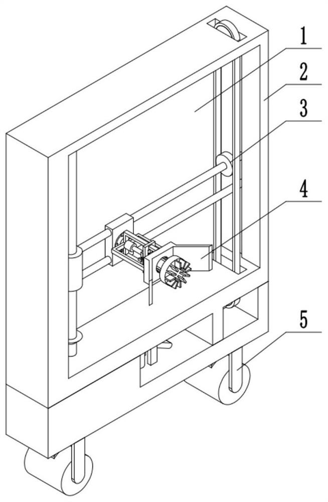
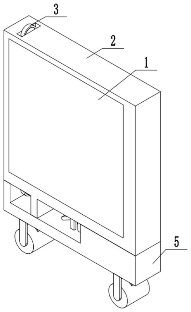
[0037] Combine below figure 1 , 2 Description of this embodiment, a wall skin cleaning device for decoration, including a movable rear panel 1, a mounting frame body 2, a driving device 3, a cleaning device 4 and a moving device 5, and the movable rear panel 1 is movably installed on the mounting frame body 2, a driving device 3 is installed on the mounting frame body 2, the cleaning device 4 is installed on the driving device 3, and the moving device 5 is fixedly installed on the mounting frame body 2.

specific Embodiment approach 2

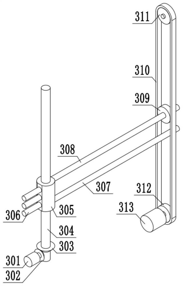
[0039] Combine below image 3 , 4 Describe this embodiment, this embodiment will further explain the first embodiment, the driving device 3 includes a power motor A301, driving bevel gear A302, driving bevel gear B303, driving screw rod A304, driving threaded sleeve 305, limiting slide bar 306, Guide bar 307, driving screw rod B308, driving pulley 309, driving belt 310, support pulley 311, driving pulley 312, power motor B313, the output end of power motor A301 is equipped with driving bevel gear A302, driving bevel gear A302 and driving bevel The gear B303 is meshed with the teeth, and the driven bevel gear B303 is fixedly installed on the driven screw rod A304, and the driven screw rod A304 is movably installed on the mounting bracket body 2, and the driven threaded sleeve 305 is installed on the driven screw rod A304, and the driven threaded sleeve 305 is fixedly installed with Restricting slide bar 306, guide rod 307 sliding installation is driven thread sleeve 305, is in...

specific Embodiment approach 3

[0041] Combine below Figure 5 , 6 , 7, 8, 9, 10, 11, 12, and 13 illustrate this embodiment, and this embodiment will further explain Embodiment 1. The described cleaning device 4 includes a fixed block 401, a driving mechanism 402, a cleaning mechanism 403, an adjustment Mechanism 404, driving mechanism 402 is installed on the fixed block body 401, driving mechanism 402 is installed on the cleaning mechanism 403, adjusting mechanism 404 is installed on the driving mechanism 402, and cleaning mechanism 403 is fixedly installed on the adjusting mechanism 404;

[0042] The driving mechanism 402 includes a control block 405, a driving column 406, a block 407, a fixed cross 408, a power motor C409, an adjusting screw 410, and a driving gear 411. The control block 405 is fixedly installed on the driving column 406, and the driving column 406 The block 407 is fixedly installed, the driving column 406 is movably installed on the fixed block 401, the fixed cross 408 is fixedly instal...


PUM


Abstract

The invention relates to a wall skin cleaning device, and particularly relates to a wall skin cleaning device for decoration. The wall skin cleaning device comprises a movable rear plate, a mounting frame body, a driving device, a cleaning device and a moving device, wherein the movable rear plate is movably mounted on the mounting frame body, the driving device is mounted on the mounting frame body, the cleaning device is mounted on the driving device, and the moving device is fixedly mounted on the mounting frame body. The wall skin cleaning device can automatically clean wall skin, liberate labor force and improve working efficiency. The wall skin cleaning device can flexibly achieve conversion between transverse cleaning and longitudinal cleaning and is higher in practicability. The wall skin cleaning device can achieve two times of cleaning through single operation and makes cleaning more thorough and smooth.

Description

technical field [0001] The invention relates to a wall skin cleaning device, in particular to a wall skin cleaning device for decoration. Background technique [0002] In decoration, wall painting is very important. The flatness of the wall directly affects the aesthetics of the interior. The walls of second-hand houses often appear peeling. At this time, if the walls are painted directly, the walls will be very uneven. Smooth, even after the wall is painted, the wall continues to peel and crack. Therefore, before the wall is painted, the wall skin must be treated. In the prior art, the cleaning of the wall skin is mostly manual cleaning, that is, the workers use flakes to remove the wall skin. , Not only will it cause a burden to the worker's body, but the dust generated during cleaning will also threaten the health of the worker, and the work efficiency is very low. Contents of the invention [0003] The technical problem mainly solved by the present invention is to pro...

Claims


Application Information

Patent Timeline
Patent Type & Authority Applications(China)
IPC IPC(8): E04G23/00E04F21/00
CPCE04G23/00E04F21/00
Inventor 郭继文
Owner 杭州飞鸟装饰工程有限公司
Learn More