
Lathe tailstock moving device

A technology of moving device and tailstock, which is applied in tailstock/top, turning equipment, tool holder accessories, etc., which can solve the problems of time-consuming, labor-intensive and production efficiency reduction

Inactive Publication Date: 2019-01-15
赵银宝
View PDF10 Cites 0 Cited by
  • Summary
  • Abstract
  • Description
  • Claims
  • Application Information

AI Technical Summary

Problems solved by technology

[0003] In view of this, the embodiment of the present invention provides a lathe tailstock moving device to improve the tailstock of the existing CNC lathe workers. When the tailstock is in operation, the tailstock can move along the bed rails, and the tailstock moves by pushing and pulling by hand. Time-consuming and labor-intensive, reducing the lack of production efficiency

Method used


Image

  • Lathe tailstock moving device
  • Lathe tailstock moving device
  • Lathe tailstock moving device

Examples


Embodiment

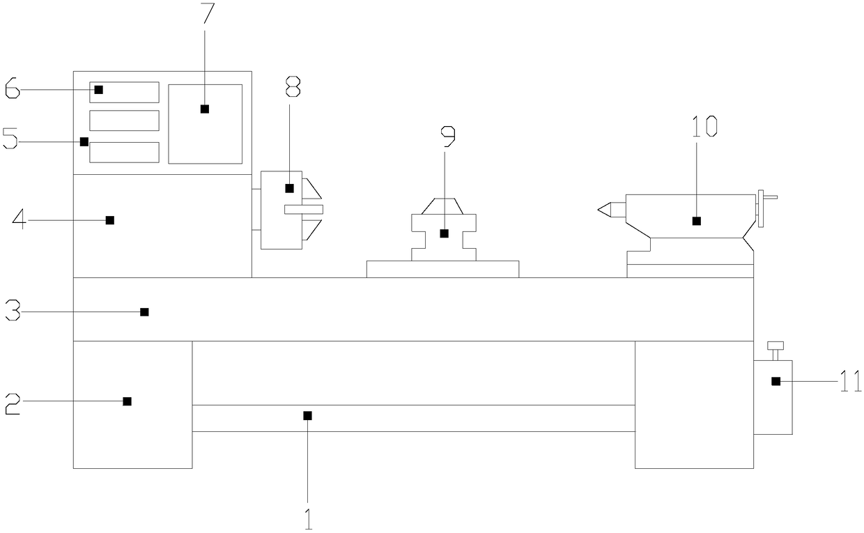
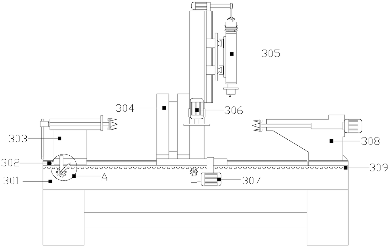
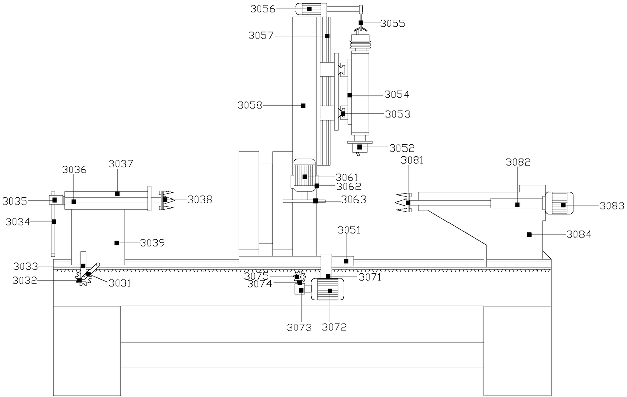
[0022] like Figure 1-Figure 5As shown, the present invention provides a lathe tailstock moving device, the structure of which includes a support rod 1, a fixed bracket 2, an efficient and fast processing mechanism 3, a spindle box 4, a control box 5, a control switch 6, a display 7, and a three-jaw chuck 8. Rotary tool holder 9, tailstock 10, lubrication box 11, the upper ends of the fixed brackets 2 are respectively welded to both sides of the bottom end of the efficient and fast processing mechanism 3, and the two ends of the support rod 1 extend horizontally to the two fixed brackets 2 The inner sides are welded together, the left side of the lubrication box 11 is fixedly welded to the right side of the fixed bracket 2, the spindle box 4 and the control box 5 are both rectangular structures, and the bottom of the spindle box 4 is fixedly welded to the upper end of the efficient and fast processing mechanism 3 On the left side, the control switch 6 is provided with more tha...


PUM


Abstract

The invention discloses a lathe tailstock moving device. The lathe tailstock moving device structurally comprises a supporting rod, fixed brackets, an efficient and quick machining mechanism, a spindle box, a control box, control switches, a display, a three-jaw chuck, a swivel tool post, a tailstock and a lubrication box. The upper ends of the fixed brackets are welded to both sides of the bottomend of the efficient and quick machining mechanism separately, the two ends of the supporting rod extend horizontally to be welded together with the inner sides of the two fixed brackets, and the left side of the lubrication box is fixedly welded to the right side of the corresponding fixing bracket. According to the lathe tailstock moving device, when a hand wheel is shaken, the supporting tailstock is driven to move along a longitudinal track through meshing of a first gear and a rack to realize longitudinal feed, a locking device needs to be arranged between the supporting tailstock and the longitudinal track so as to fix the supporting tailstock in any longitudinal position where positioning is required, meanwhile, a second gear is driven by a third motor to rotate, when the third motor rotates, a sliding seat is driven to move along the longitudinal track through meshing of the second gear and the rack to realize longitudinal feed.

Description

technical field [0001] The invention relates to a moving device for a lathe tailstock, which belongs to the field of moving devices for a lathe tailstock. Background technique [0002] With the rapid development of our country's national economy, there is an increasing demand for heavy-duty machine tools. In heavy-duty CNC horizontal lathes, the tailstock mainly plays the role of tightening and supporting the workpiece, and according to the length of the workpiece processed by the machine tool, the moving tailstock The seat system realizes the supporting ability to the workpiece. For the heavy-duty horizontal lathe, the traditional tailstock structure has insufficient torque transmission, and it is inconvenient to move and fix the tailstock on the bed, so it cannot play a good jacking effect. However, when the existing CNC lathe worker's tailstock is in operation, the tailstock can move along the guide rail of the bed, and the tailstock moves by pushing and pulling by hand, ...

Claims


Application Information

Patent Timeline
IPC IPC(8): B23B23/00
Inventor 赵银宝
Owner 赵银宝
Learn More