Short pipe outer circle grinding device for factory machining
A short tube and factory technology, which is applied in the field of short tube cylindrical grinding devices, can solve the problems of laborious, easy impact of the grinding wheel on the fixture, time-consuming and other problems
- Summary
- Abstract
- Description
- Claims
- Application Information
AI Technical Summary
Problems solved by technology
Method used
Image
Examples
specific Embodiment approach 1
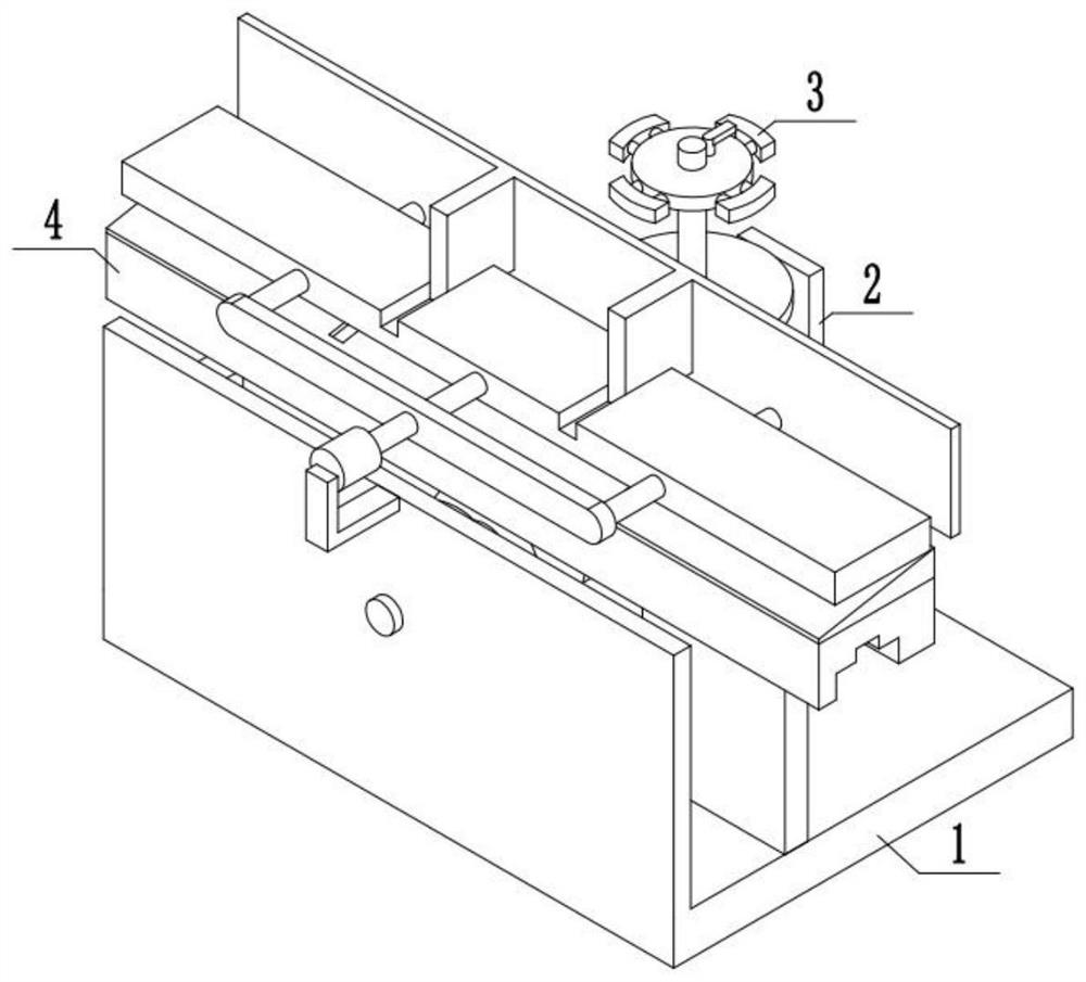
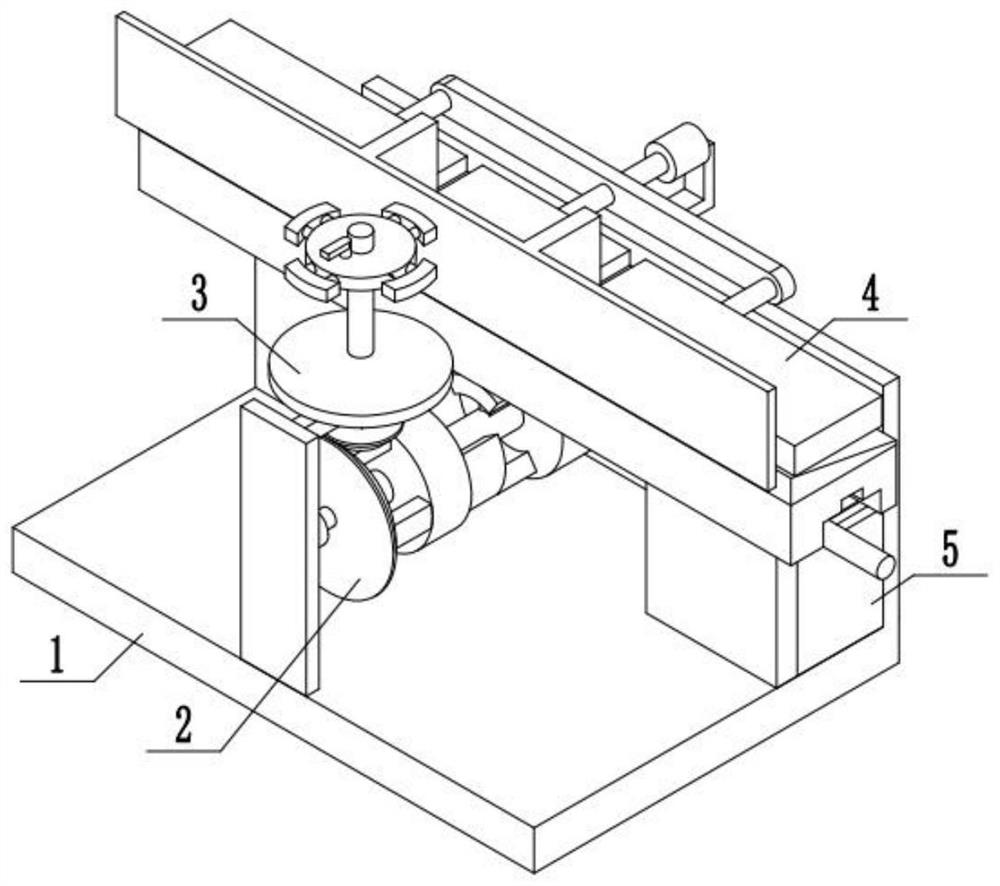
[0037] Combine below figure 1 , 2 , 3 Description of the present embodiment, a short pipe cylindrical grinding device for factory processing, including a fixed support base 1, a power device 2, a pipe clamping device 3, a pipe grinding device 4 and a feed control device 5, the fixed A power device 2 is fixedly installed on the support base 1, a pipe clamping device 3 is installed on the power device 2, a pipe grinding device 4 is fixedly installed on the fixed support base 1, and a feed control device 5 is fixedly installed on the fixed support base 1. The feed control device 5 is installed on the pipe grinding device 4;
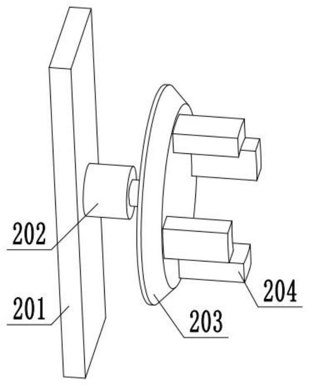
[0038] The power device 2 includes an installation vertical plate 201, a power motor A202, a transmission bevel gear plate 203, and a gear plate connecting frame 204. The installation vertical plate 201 is fixedly installed on the fixed support base 1, and the power motor A202 is fixedly installed on the installation vertical plate 201, the output end of t...
specific Embodiment approach 2
[0040] Combine below Figure 4 , 5 , 6, 7, and 8 illustrate this embodiment, and this embodiment will further explain Embodiment 1. The pipe clamping device 3 includes a transmission bevel gear 301, a pipe placement plate 302, a connecting screw 303, a screw fixing frame 304, a pipe The fixing mechanism 305, the control handle 306, the transmission bevel gear 301 are fixedly installed on the connecting screw 303, the connecting screw 303 is fixedly installed with a pipe placement plate 302, the screw fixing frame 304 is fixedly installed on the installation vertical plate 201, and the screw fixing frame 304 A connecting screw 303 is installed movable, the pipe fixing mechanism 305 is installed on the connecting screw 303 through threads, and the control handle 306 is fixedly installed on the pipe fixing mechanism 305;
[0041] The pipe fixing mechanism 305 includes a clamping plate 307, an extension rod 308, and an extension plate 309. An extension rod 308 is slidably install...
specific Embodiment approach 3
[0043] Combine below Figure 9 , 10 , 11, 12, 13, 14, 15 illustrate this embodiment, and this embodiment will further explain Embodiment 1. The pipe grinding device 4 includes a driving mechanism 401, a grinding mechanism 402, an installation side plate 403, and a fixed guide plate 404 , the driving mechanism 401 is connected with the grinding mechanism 402, the grinding mechanism 402 is installed on the installation side plate 403, the driving mechanism 401 is movably installed on the installation side plate 403, the fixed guide plate 404 is fixedly installed on the fixed support base 1, and the fixed guide plate Grinding mechanism 402 is slidably installed on 404;
[0044] The driving mechanism 401 includes a driving wheel 405, a driving arc frame A406, a connecting shaft 407, a driving arc frame B408, and a compound gear 409. The driving wheel 405 is fixedly installed on the gear plate connecting frame 204, and the driving wheel 405 is fixedly installed There is a driving...
PUM
 Abstract
Description
Claims
Application Information
 - R&D
- Intellectual Property
- Life Sciences
- Materials
- Tech Scout
- Unparalleled Data Quality
- Higher Quality Content
- 60% Fewer Hallucinations
Browse by: Latest US Patents, China's latest patents, Technical Efficacy Thesaurus, Application Domain, Technology Topic, Popular Technical Reports.
© 2025 PatSnap. All rights reserved.Legal|Privacy policy|Modern Slavery Act Transparency Statement|Sitemap|About US| Contact US: help@patsnap.com


