Car roof camera system

A technology of camera system and camera equipment, which is applied in closed-circuit television system, image communication, vehicle parts, etc., can solve problems such as inability to detect in real time, and achieve the effect of good night vision function

Inactive Publication Date: 2020-11-24
NANJING UNIV OF INFORMATION SCI & TECH
View PDF5 Cites 1 Cited by
  • Summary
  • Abstract
  • Description
  • Claims
  • Application Information

AI Technical Summary

Problems solved by technology

In the normal driving process of the vehicle, most of these cameras are not working, and cannot detect the blind spot in real time.

Method used


Image

  • Car roof camera system
  • Car roof camera system

Examples


Embodiment Construction

[0018] In order to make the technical solutions and advantages of the present invention clearer, the present invention will be further described in detail below in conjunction with the accompanying drawings.

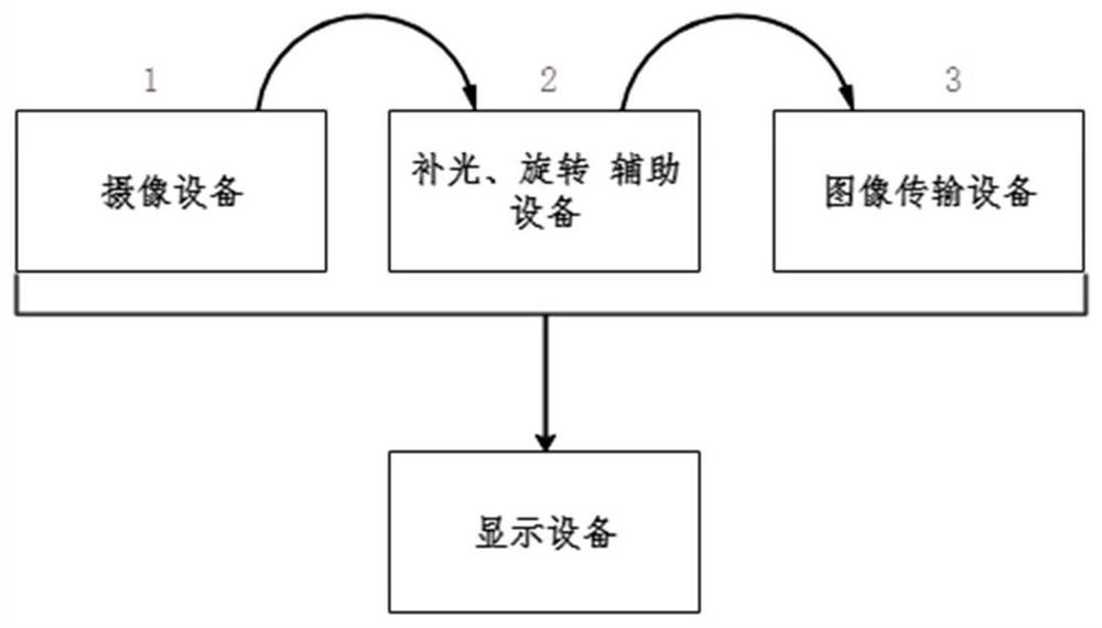
[0019] Such as figure 1 The shown vehicle roof camera system according to a specific embodiment of the present invention can be divided into camera equipment, supplementary light / rotation auxiliary equipment, image transmission equipment and display equipment according to modules.

[0020] Such as figure 1 As shown, the camera equipment assists in imaging through supplementary light / rotation equipment, and then the image transmission equipment transmits it to the central control display screen, mobile phone and other terminals in real time.

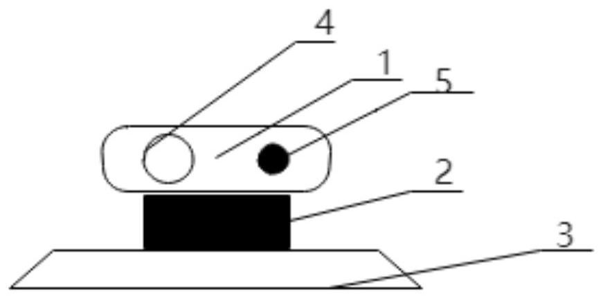
[0021] Such as figure 2 Shown is a car roof camera system, including a chassis installed on the roof of the car, a rotating pan-tilt, and a camera equipment box. The base is fixed at the rear position of the roof. The rotating ...


PUM


Abstract

The invention discloses a car roof camera system. The car roof camera system comprises a camera equipment box, a rotary pan-tilt and a base plate; the camera equipment box comprises a wide-angle camera and a light supplement lamp, and can shoot clear images of a rear vehicle; the camera equipment box is installed on the rotary pan-tilt, so that the shooting direction of a camera can be adjusted asrequired during use, and an area needing to be monitored can be adjusted more flexibly; the base plate is installed at the rear position of a car roof, and a wireless transmission module is arrangedin the base plate and can transmit the images to an in-vehicle device in real time so that a driver can observe the condition outside the vehicle. According to the car roof camera system, the car roofcamera system can detect the rear vehicle condition in real time in the driving process, the blind area which cannot be monitored by conventional rear vehicle camera equipment is solved, and the driving safety is improved.

Description

technical field [0001] The invention relates to the field of automobiles, in particular to a vehicle roof camera system. Background technique [0002] Car panoramic cameras have been widely used in vehicles. However, the current car body surround view equipment adds multiple cameras on the front and side of the car body, and the environment around the car can be viewed through the car display screen, but there is still a blind spot for the rear car. [0003] Now, the camera on the car is mainly used in the driving process of the vehicle to assist the driver to observe the environment of the rear vehicle, especially the place (blind spot) that the driver cannot observe and is inconvenient to observe during driving, so as to improve the safety of the vehicle. In the normal driving process of the vehicle, most of these cameras are not working, and cannot detect the blind spot in real time. The system can also assist the driver to monitor the car's starting / parking situation, ...

Claims


Application Information

Patent Timeline
Patent Type & Authority Applications(China)
IPC IPC(8): B60R1/06H04N7/18
CPCB60R1/06H04N7/183
Inventor 张凯王晔
Owner NANJING UNIV OF INFORMATION SCI & TECH
Why Eureka
Try Eureka