Cutting treatment device for building-used bars and pipes

A processing device and cutting device technology, applied in sawing machine devices, metal sawing equipment, metal processing equipment, etc., can solve the problems of bar or pipe pinching, different lengths, and poor adjustment of the inclination angle.

Inactive Publication Date: 2020-11-27
哈尔滨金玉钰科技开发有限公司
View PDF0 Cites 0 Cited by
  • Summary
  • Abstract
  • Description
  • Claims
  • Application Information

AI Technical Summary

Problems solved by technology

[0002] Both rods and pipes are of different lengths, and they need to be cut before use. According to the use requirements, the end faces of the rods or pipes are processed on a plane or an inclined plane. There are many disadv

Method used


Image

  • Cutting treatment device for building-used bars and pipes
  • Cutting treatment device for building-used bars and pipes
  • Cutting treatment device for building-used bars and pipes

Examples


specific Embodiment approach 1

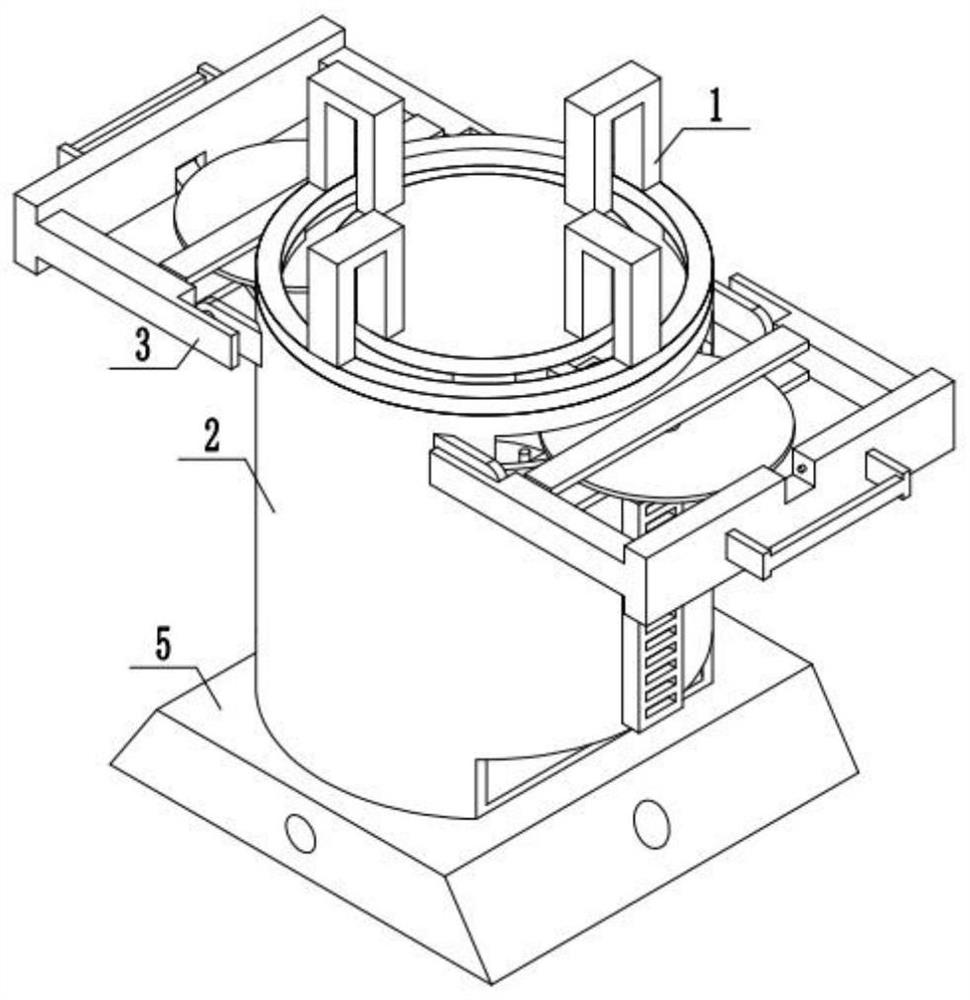
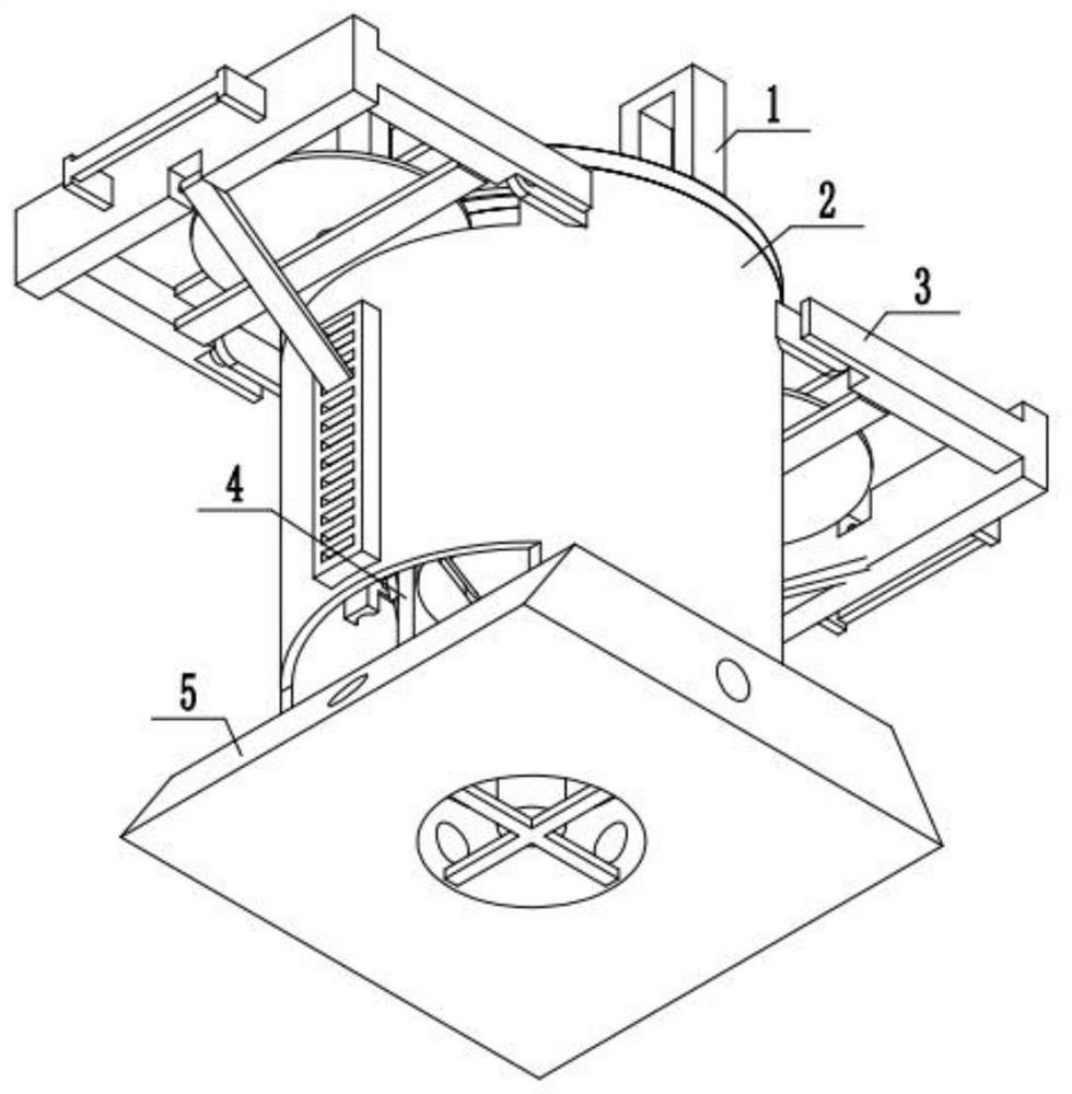
[0038] Combine below figure 1 , 2Description of this embodiment, a device for cutting and processing rods and pipes for construction, including a device upper cover body 1, a cutting outer shell 2, a cutting device 3, a rod and pipe driving device 4 and a device fixing base 5, and the device is installed on the fixing base 1 There is a protective outer shell 2, the device upper cover 1 is located above the cutting outer shell 2, the cutting device 3 is fixedly installed on the protective outer shell 2, the rod and pipe driving device 4 is fixedly installed above the device fixing base 5, and the cutting device 3 On the device fixed base 5.

specific Embodiment approach 2

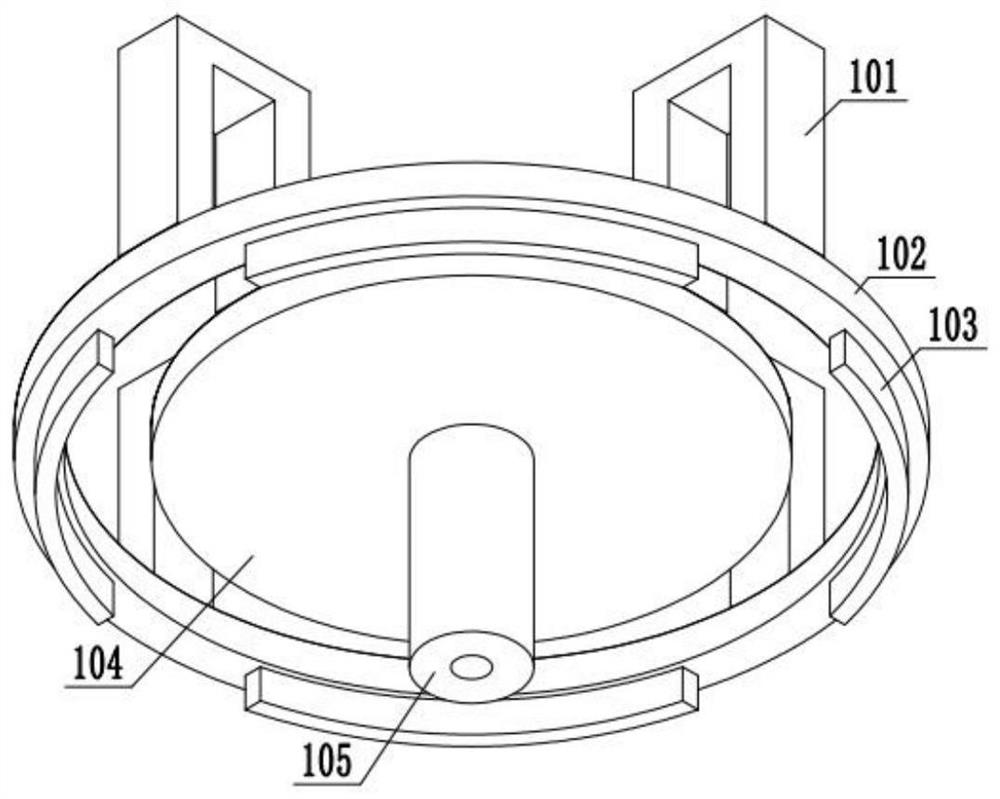
[0040] Combine below image 3 , 4 Describe this embodiment, this embodiment will further explain Embodiment 1, the upper cover body 1 of the device includes an avoidance connecting frame 101, an outer cover body 102, an arc-shaped block 103, an inner cover body 104, and a connecting shaft sleeve 105, The avoidance connecting frame 101 is fixedly installed on the outer cover body 102, and the below of the outer cover body 102 is fixedly equipped with an arc-shaped block 103, and the inner cover body 104 is fixedly installed on the avoiding connecting frame 101, and the avoiding connecting frame 101 is provided with four, each The cloth is installed on the inner cover body 104, and the connecting shaft sleeve 105 is fixedly installed under the connecting shaft sleeve 105. The connecting shaft sleeve 105 is set on the rod and pipe driving device 4, which can prevent the vibration of the rod and pipe driving device 4 and avoid the connection. The frame 101 is set in an arched sha...

specific Embodiment approach 3

[0042] Combine below Figure 5 , 6 Describe this embodiment, this embodiment will further explain Embodiment 1. The cutting device 3 includes a connecting block 301, a driving frame 302, a driving handle 303, a fixed connecting frame 304, a power motor A305, a cutting saw blade 306, and an adjusting rod 307, fixed clamping plate 308, connecting block 301 is fixedly installed on the protective shell body 2, two connecting blocks 301 are provided, the driving frame 302 is installed on the connecting block 301 through the movement of the shaft, and the driving frame 302 is fixedly installed with a driving handle 303 , the fixed connecting frame 304 is fixedly installed on the driving frame 302, the power motor A305 is fixedly installed on the driving frame 302, the output end of the power motor A305 is equipped with a cutting saw blade 306, and the cutting saw blade 306 is installed on the fixed connecting frame 304 through the shaft. On the top, the adjusting rod 307 is install...


PUM


Abstract

The invention relates a cutting device for bars and pipes, in particular to a cutting treatment device for building-used bars and pipes. The cutting treatment device for the building-used bars and pipes comprises a device upper cover body, a cutting outer shell, a cutting device, a bar-pipe driving device and a device fixing base. A protective outer shell is installed on a device fixing baseplate.The device upper cover body is located above the cutting outer shell. The cutting device is fixedly installed on the protective outer shell. The bar-pipe driving device is fixedly installed above thedevice fixing base. The cutting device is arranged on the device fixing base.

Description

technical field [0001] The invention relates to a bar and pipe cutting device, more specifically a bar and pipe cutting and processing device for construction. Background technique [0002] Both rods and pipes are of different lengths, and they need to be cut before use. According to the use requirements, the end faces of the rods or pipes are processed on a plane or an inclined plane. There are many disadvantages in the processing of pipes: the prior art is not easy to adjust the inclination angle of the bar or the inclined plane of the pipe, and the prior art is easy to pinch the bar or the pipe. Contents of the invention [0003] The main technical problem to be solved by the present invention is to provide a device for cutting and processing rods and pipes for construction. 1. The device can automatically clamp rods or pipes without pinching; 2. The device can accurately adjust the cutting surface Angle of inclination; 3. This device utilizes groove feed, which can ma...

Claims


Application Information

Patent Timeline
IPC IPC(8): B23D45/00B23D45/12B23D47/04
CPCB23D45/00B23D45/12B23D47/04
Inventor 蔡吉安
Owner 哈尔滨金玉钰科技开发有限公司
Why Eureka
Try Eureka