Multifunctional board conveying and transporting device
A transportation device and a multi-functional technology, which is applied in the field of multi-functional plate conveying and transportation devices, can solve problems such as time-consuming and labor-consuming, potential safety hazards, and waist injuries of staff
- Summary
- Abstract
- Description
- Claims
- Application Information
AI Technical Summary
Problems solved by technology
Method used
Image
Examples
specific Embodiment approach 1
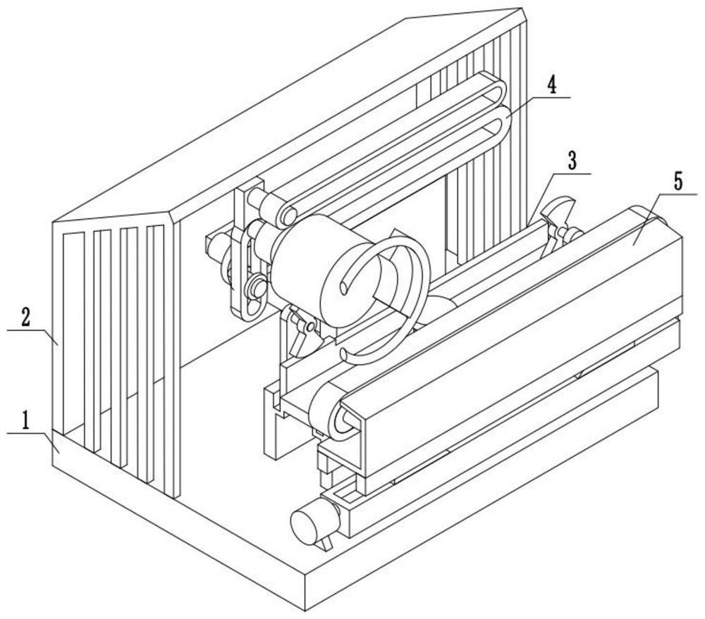
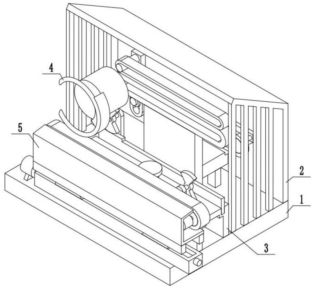
[0035] Combine below figure 1 , 2Description of this embodiment, a multi-functional plate transporting device, including a device fixing base plate 1 and a protective outer shell 2, a protective outer shell 2 is fixedly installed above the device fixing base plate 1, and also includes a driving device 3, a plate material conveying device 4 and Auxiliary transport device 5, driving device 3 is fixedly installed on the top of the device fixed base plate 1, sheet metal conveying device 4 is fixedly installed on the top of the device fixed base plate 1, and auxiliary transport device 5 is fixedly installed on the top of the device fixed base plate 1.
specific Embodiment approach 2
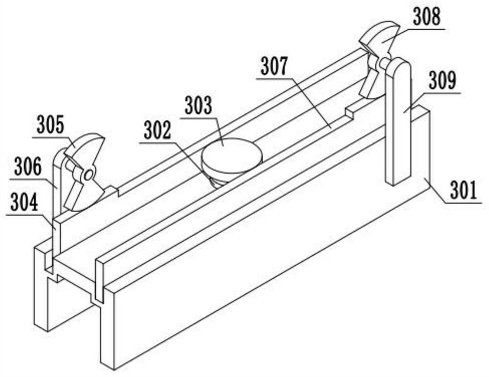
[0037] Combine below image 3 , 4 Describe this embodiment, this embodiment will further explain Embodiment 1, the driving device 3 includes a fixed chassis 301, a forward and reverse motor 302, a transmission gear A303, a driving rack A304, an incomplete gear A305, and a gear fixing frame A306, driving rack B307, incomplete gear B308, gear fixed frame B309, fixed base frame 301 is fixedly installed on the device fixed base plate 1, fixed base frame 301 is fixedly installed with forward and reverse motor 302, transmission gear A303 is installed on positive At the output end of the reversing motor 302, the transmission gear A303 meshes with the driving rack A304 through the teeth, and the driving rack A304 is slidably installed on the fixed chassis 301, and the driving rack A304 meshes with the incomplete gear A305 through the teeth. The gear A305 is installed on the gear fixing frame A306 through the shaft movement, the gear fixing frame A306 is fixedly installed on the fixed...
specific Embodiment approach 3
[0040] Combine below Figure 5 , 6 , 7, 8, and 9 illustrate this embodiment, and this embodiment will further explain Embodiment 1. The plate conveying device 4 includes a fixed bracket A401, a fixed bracket B402, a transmission device 403, a transmission gear B404, a connecting frame 405, a transport The ring 406, the fixed bracket A401 is fixedly installed on the fixed base plate 1 of the device, the fixed bracket B402 is fixedly installed on the fixed base plate 1 of the device, the transmission device 403 is fixedly installed on the fixed bracket A401, the transmission device 403 is fixedly installed on the fixed bracket B402, and the transmission The gear B404 is installed on the transmission device 403, the connecting frame 405 is fixedly installed on the transmission gear B404, and the connecting frame 405 is fixedly installed with a transport ring 406;
[0041] The transmission device 403 includes a guide sleeve A407, a guide sleeve B408, a sliding rod A409, a guide s...
PUM
 Abstract
Description
Claims
Application Information
 - R&D
- Intellectual Property
- Life Sciences
- Materials
- Tech Scout
- Unparalleled Data Quality
- Higher Quality Content
- 60% Fewer Hallucinations
Browse by: Latest US Patents, China's latest patents, Technical Efficacy Thesaurus, Application Domain, Technology Topic, Popular Technical Reports.
© 2025 PatSnap. All rights reserved.Legal|Privacy policy|Modern Slavery Act Transparency Statement|Sitemap|About US| Contact US: help@patsnap.com


