

Dynamic QR code display terminal
A dynamic two-dimensional code and display terminal technology, applied in electromagnetic radiation induction, instruments, induction recording carriers, etc., can solve the problems of inconvenient portability, complex overall structure, inability to scan and display two-dimensional codes at the same time, and achieve easy portability. , the overall compact effect
- Summary
- Abstract
- Description
- Claims
- Application Information
AI Technical Summary
Problems solved by technology
Method used
Image

Examples
Embodiment 1
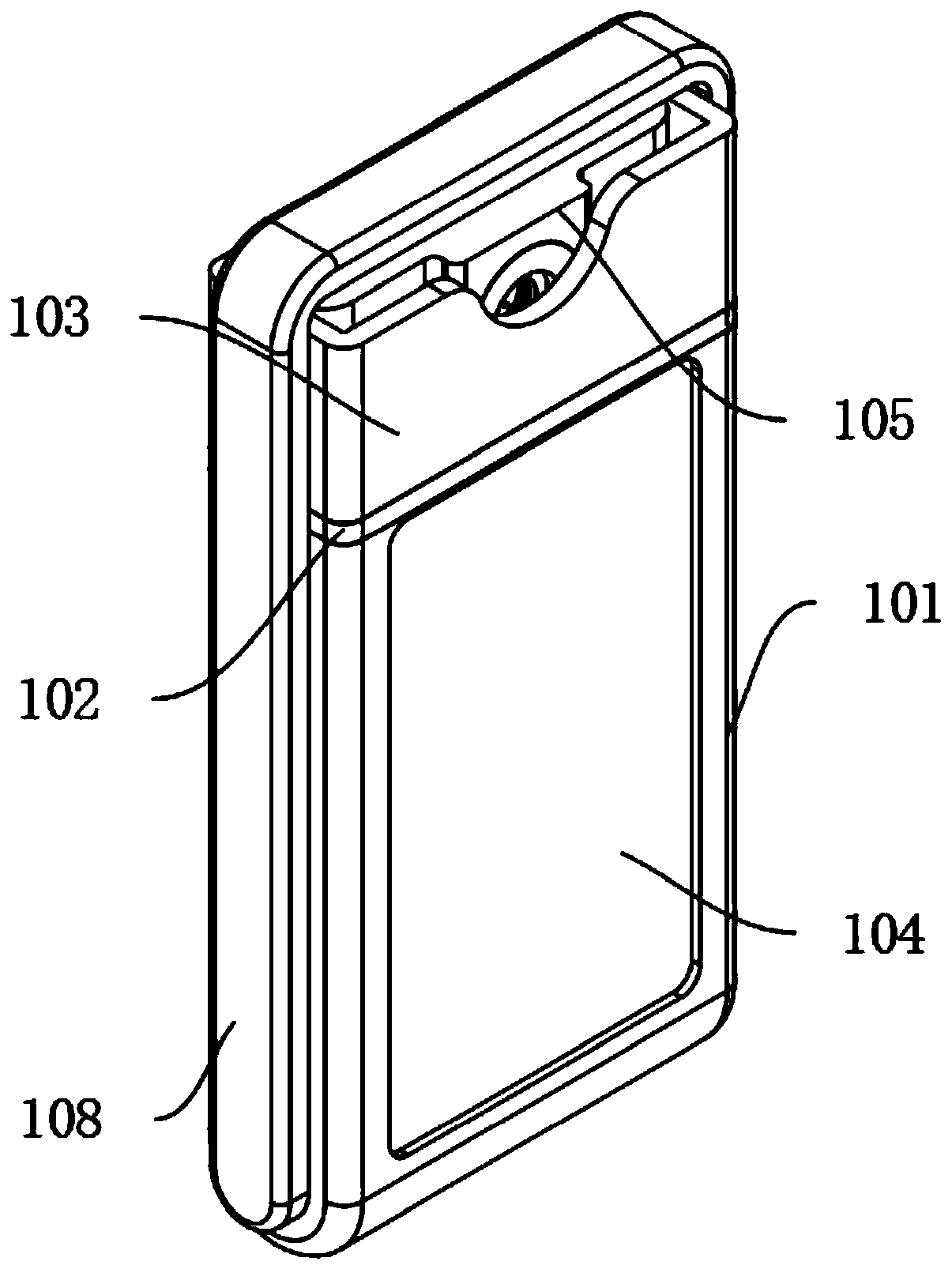
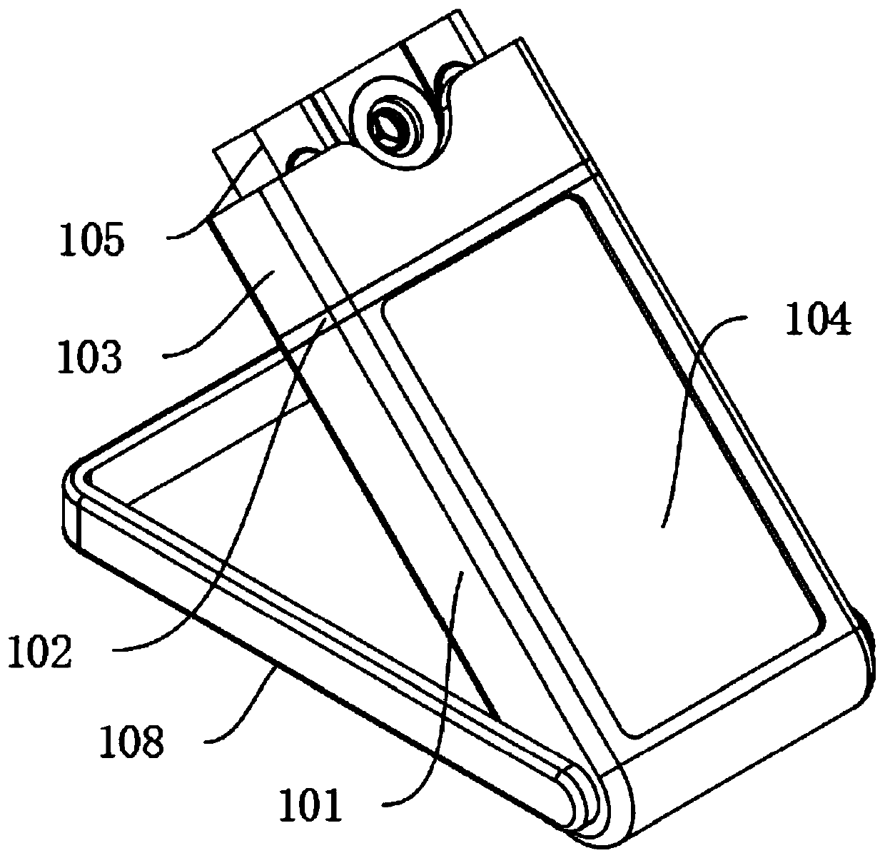
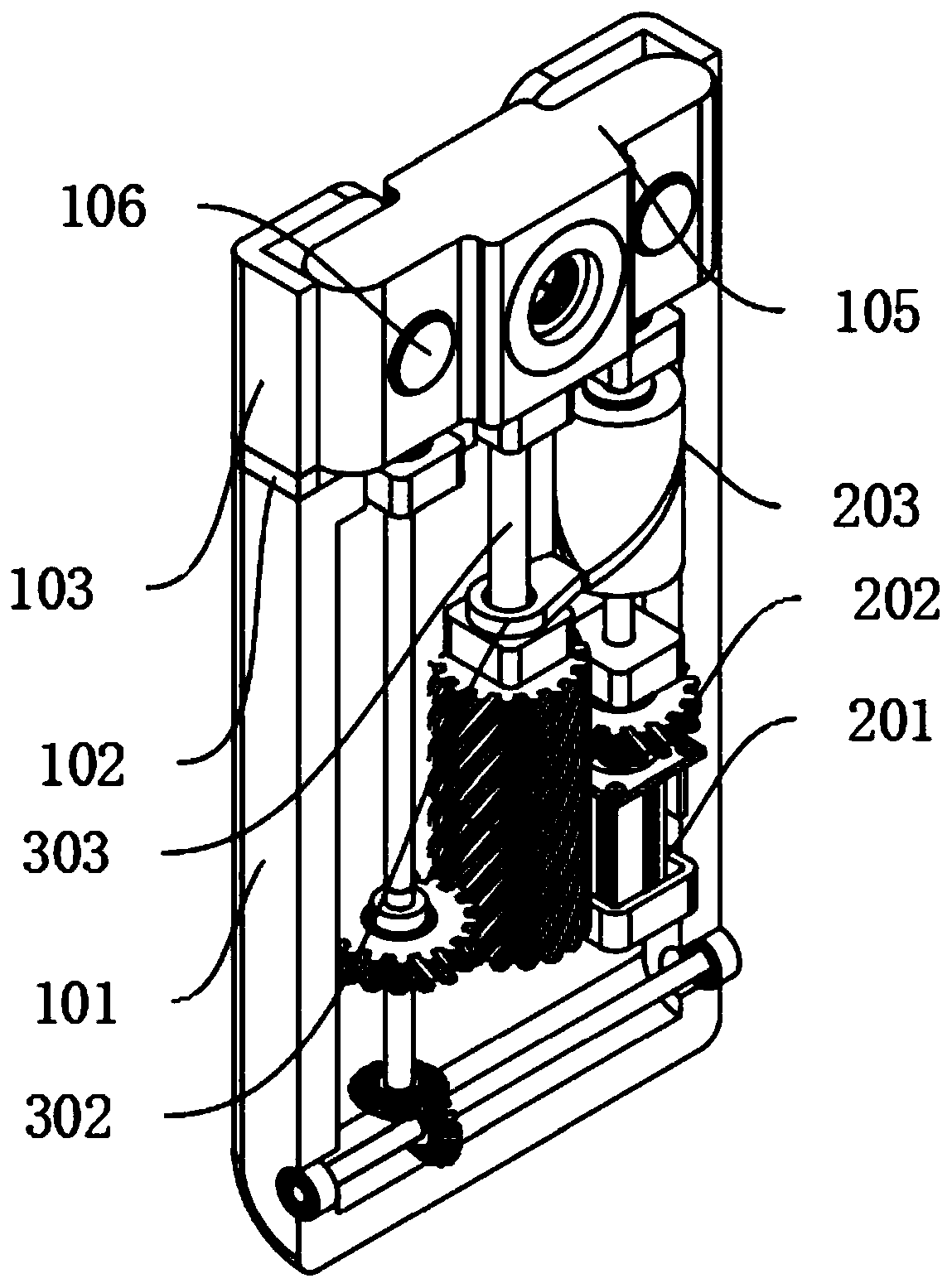
[0027] A dynamic two-dimensional code display terminal, comprising: a main body housing 101, a connecting housing 102 and a limiting housing 103, the upper end of the main housing 101 is fixedly connected to the lower end of the connecting housing 102, the upper end of the connecting housing 102 is fixedly connected to the lower end of the limiting housing 103, the main body A two-dimensional code display screen 104 is arranged on the front side of the housing 101, and an internal driving mechanism is fixedly installed on the right side of the main body housing 101. Flexible connection, the two-dimensional code scanning device 105 is movably socketed inside the limit housing 103, the left and right sides of the two-dimensional code scanning device 105 are fixedly installed with speakers 106, and the inner middle end of the two-dimensional code scanning device 105 is provided with a fixed groove 107, The rear end of the fixed slot 107 is fixedly equipped with a scanning camera 1...
Embodiment 2
[0029] Embodiment 2: Based on Embodiment 1, the difference is:
[0030] The internal driving mechanism includes: a motor 201, a rotating gear 202 and a rotating cylinder 203. The motor 201 is fixedly installed in the lower left corner of the main body shell 101. The main shaft of the motor 201 is fixedly installed with a rotating gear 202 and a rotating cylinder 203 from bottom to top. The main shaft of the motor 201 The upper end is movably connected with the inner wall of the main body shell 101, and the rotating gear 202 is meshed and connected with the mobile driving mechanism.
[0031] The mobile driving mechanism includes: a rotating wheel 301, a moving block 302 and a moving shaft 303. The rotating gear 202 is meshed with the rotating wheel 301. The upper end of the rotating wheel 301 is fixedly connected to the lower end of the moving shaft 303. The upper end of the moving shaft 303 runs through the main body shell 101 and the The lower end of the middle part of the tw...
Embodiment 3
[0035] Embodiment 3: Based on Embodiment 1 and 2, but the difference is:
[0036] The rotation support mechanism includes: a transmission gear 501, a transmission shaft 502, a transmission helical gear 503, a rotation helical gear 504 and a rotation shaft 505, the rotation wheel 301 is meshed with the transmission gear 501, the shaft center of the transmission gear 501 is fixedly connected with the transmission shaft 502, and the transmission The upper and lower ends of the shaft 502 are movably connected to the inner wall of the main body casing 101, the lower end of the transmission shaft 502 is fixedly connected to the axis center of the transmission helical gear 503, the transmission helical gear 503 is meshed with the rotation helical gear 504, and the axis center of the rotation helical gear 504 is fixed to the rotation shaft 505 Connection, the left and right ends of the rotating shaft 505 pass through the main body shell 101 and are fixedly connected with the lower ends...
PUM
 Abstract
Description
Claims
Application Information