Energy-saving circulating drying facility
A technology of drying equipment and circulating air ducts, applied in the field of drying, which can solve the problems of high drying cost, slow drying speed of clothes, and large energy consumption, so as to speed up the flow speed, increase the gap, and avoid drying slower effect
- Summary
- Abstract
- Description
- Claims
- Application Information
AI Technical Summary
Problems solved by technology
Method used
Image

Examples
Embodiment 1
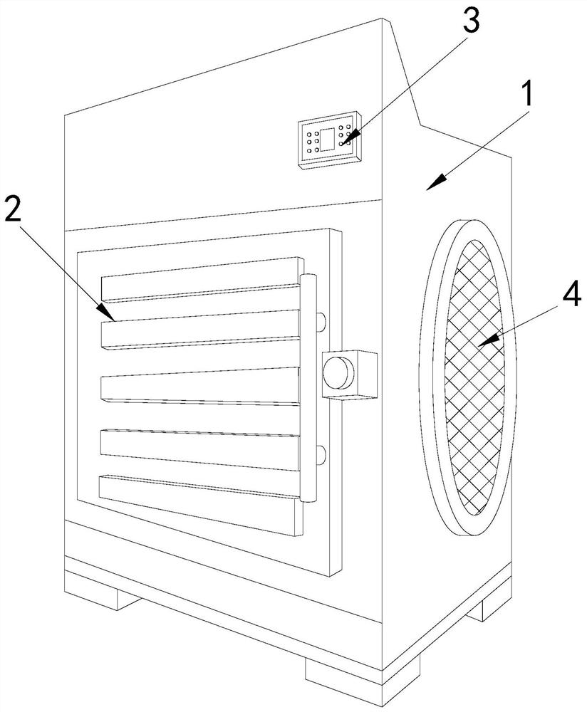
[0026] Example 1: Please refer to Figure 1-Figure 5 , the specific embodiments of the present invention are as follows:
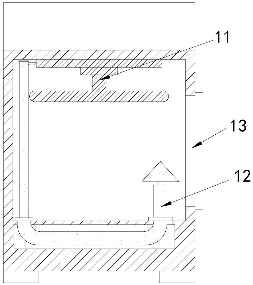
[0027] Its structure includes a main body 1, a box door 2, a control panel 3, and an air inlet 4. The front end of the main body 1 is provided with a box door 2, the control panel 3 is located at the front upper end of the main body 1, and the air inlet 4 is arranged on the main body. 1, the main body 1 includes a clothes drying device 11, a circulating air duct 12, and an air inlet block 13, the clothes drying device 11 is arranged on the inner top of the main body 1, and one end of the circulating air duct 12 is connected to the main body 1, the other end is connected to the side end of the clothes drying device 11, and the air inlet block 13 is arranged at the inner side end of the main body 1.
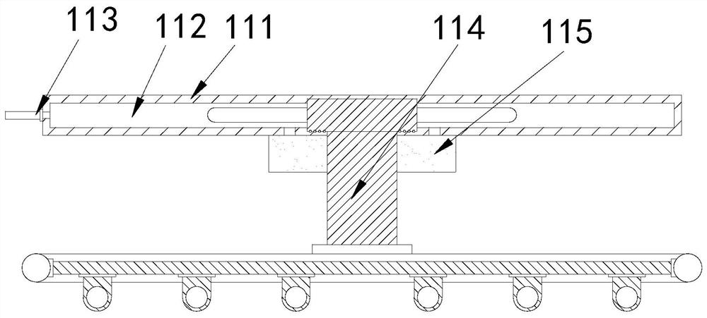
[0028] The clothes drying device 11 comprises an air guiding device 111, an empty slot 112, an air inlet pipe 113, a clothes hanger 114, and an air guiding bl...
Embodiment 2
[0032] Example 2: Please refer to Figure 6-Figure 8 , the specific embodiments of the present invention are as follows:
[0033] The air guide block 115 includes a penetration hole b1, an air guide groove b2, a rotating blade b3, and a splitter hole b4. The penetration hole b1 is arranged in the middle of the air guide block 115, and the air guide groove b2 is provided with one, and located at both ends of the top of the air guide block 115, the rotating blade b3 is installed in the air guide groove b2, the said split hole b4 is provided with eight, and is respectively arranged at the bottom of the air guide groove b2, the rotating The blade b3 is engaged in the air guide groove b2, which facilitates the rotation of the rotating blade b3 driven by the airflow, so that the airflow enters the flow distribution hole b4 in a vortex shape.
[0034] The distribution hole b4 includes a hole body b41, a return block b42, and an air outlet block b43. More than ten return blocks b42 a...
PUM
 Abstract
Description
Claims
Application Information
 - R&D
- Intellectual Property
- Life Sciences
- Materials
- Tech Scout
- Unparalleled Data Quality
- Higher Quality Content
- 60% Fewer Hallucinations
Browse by: Latest US Patents, China's latest patents, Technical Efficacy Thesaurus, Application Domain, Technology Topic, Popular Technical Reports.
© 2025 PatSnap. All rights reserved.Legal|Privacy policy|Modern Slavery Act Transparency Statement|Sitemap|About US| Contact US: help@patsnap.com