Cast-in-place box girder integrated construction equipment and construction method thereof

A box girder and cast-in-place technology, which is applied in bridge construction, bridges, buildings, etc., can solve problems such as difficulty in meeting social needs, inability to work in parallel, and insufficient advantages, achieving significant social and economic effects and reducing the intensity of manpower operations , Improve the effect of site utilization

Inactive Publication Date: 2020-11-27
CCCC SECOND HARBOR ENG +1
View PDF14 Cites 7 Cited by
  • Summary
  • Abstract
  • Description
  • Claims
  • Application Information

AI Technical Summary

Problems solved by technology

[0006] The traditional construction method of cast-in-place box girder mainly includes the following defects: many construction procedures and long construction period; various construction procedures are mechanized and automated, the demand for manpower is large, and safety and quality control are difficult
[0011] The current mobile formwork construction technology does not essentially solve the problem that steel bar binding and concrete pouring cannot be performed in parallel, and cannot achieve the construction efficiency of factory-like assembly line operations, and the degree of functional integration is low
The advantages of the cast-in-place box girder manufacturing technology based on mobile formwork in terms of quality improvement and shortened construction period are still not significant enough, and it is difficult to meet the growing social needs. The demand for more efficient cast-in-place box girder construction technology is increasingly urgent

Method used


Image

  • Cast-in-place box girder integrated construction equipment and construction method thereof
  • Cast-in-place box girder integrated construction equipment and construction method thereof
  • Cast-in-place box girder integrated construction equipment and construction method thereof

Examples


Embodiment Construction

[0062] The present invention will be further described in detail below in conjunction with the accompanying drawings, so that those skilled in the art can implement it with reference to the description.

[0063] In the description of the present invention, the terms "transverse", "longitudinal", "upper", "lower", "front", "rear", "left", "right", "vertical", "horizontal", " The orientations or positional relationships indicated by "top", "bottom", "inner", "outer", etc. are based on the orientations or positional relationships shown in the drawings, and are only for the convenience of describing the present invention and simplifying the description, and are not indicative or implied. It should not be construed as limiting the invention that a device or element must have a particular orientation, be constructed, and operate in a particular orientation.

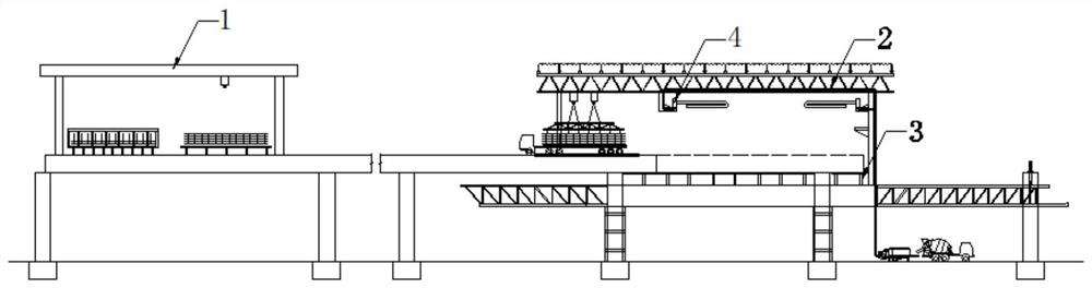
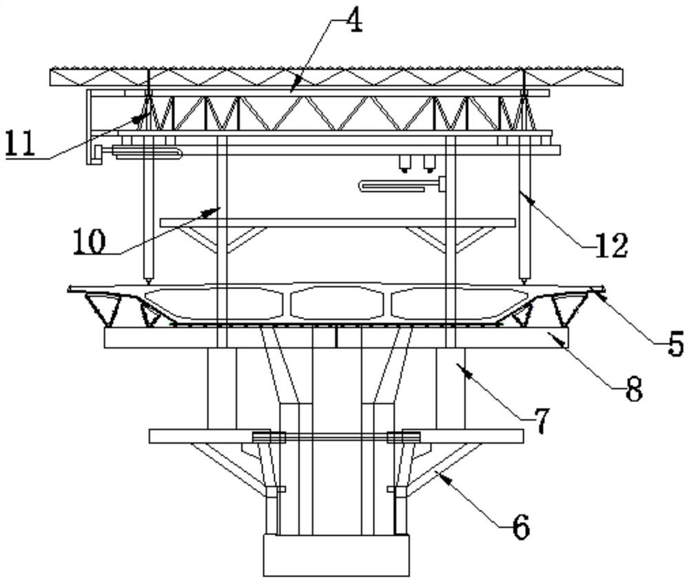
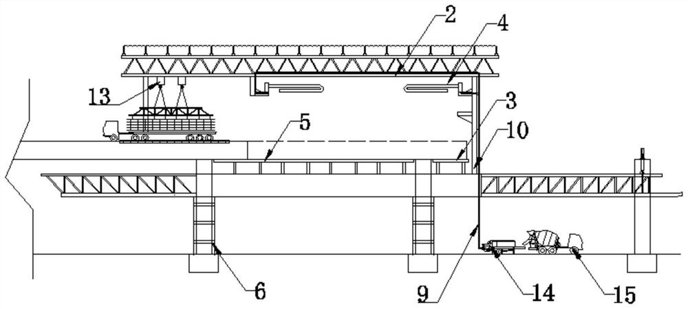
[0064] Such as Figure 1-4 As shown, a cast-in-place box girder integrated construction equipment includes a processing work...


PUM


Abstract

The invention discloses cast-in-place box girder integrated construction equipment and a construction method thereof. The cast-in-place box girder integrated construction equipment comprises a machining workshop, a movable formwork, an on-girder trolley, a material distribution system, a ramming vibration system and a surface finishing system which are sequentially arranged in a longitudinal bridge direction of a cast-in-place box girder bridge surface. The machining workshop is used for processing a steel bar component required by the cast-in-place box girder; the movable formwork is used forforming a pouring formwork structure of a box girder segment to be poured; the on-girder trolley is used for transferring a template on a poured box girder section and the reinforcing steel bar component to a to-be-poured box girder section where the movable formwork is located; the material distribution system is used for pouring concrete; the ramming vibration system is used for tamping and vibrating concrete; and the surface finishing system is used for finishing and leveling the poured surfaces of the poured box girder sections after pouring. The equipment and the method can be widely applied to the technical field of building construction equipment.

Description

technical field [0001] The invention relates to the technical field of building construction equipment. More specifically, the present invention relates to a cast-in-situ box girder integrated construction equipment and a construction method thereof. Background technique [0002] Techniques used in the field: [0003] Cast-in-place box girder is a widely used form of main beam. It adopts one-time pouring method and has good structural integrity. In the construction structure of cast-in-place box girder, the box girder directly falls on the pier column, and there is no need to set the pier top cover beam, which can be It reduces the overall height of the bridge and is widely used in urban bridges. [0004] The traditional construction method of cast-in-place box girder is mainly the bracket method, including the following steps: foundation treatment, bracket erection, formwork installation, steel bar binding and prestressed pipeline installation, concrete pouring and mainte...

Claims


Application Information

Patent Timeline
Patent Type & Authority Applications(China)
IPC IPC(8): E01D21/00E01D2/04
CPCE01D21/00E01D2/04
Inventor 陈鸣薛志武孙策李长林吴建明郑和晖王敏夏熙刘景红林国辉赖祺宇于晓洧戴书学夏昊巫兴发肖林田飞李刚代浩陈飞翔
Owner CCCC SECOND HARBOR ENG
Why Eureka
Try Eureka