Keyless lock cylinder

A keyless lock, lock cylinder technology, applied in the direction of turning key locks, combination locks, building locks, etc., can solve the problems of easy to be unlocked by tools, lost, easy to damage keys, etc., to achieve good anti-theft effect, solve easy damage and easily lost effects

Active Publication Date: 2020-11-27
雷关东
View PDF6 Cites 0 Cited by
  • Summary
  • Abstract
  • Description
  • Claims
  • Application Information

AI Technical Summary

Problems solved by technology

[0003] The purpose of the present invention is to provide a keyless lock cylinder to solve the problems of the existing pin locks and shrapnel locks proposed in the above-mentioned background technology, which are easy to be unlocked by tools, and the key is easy to be damaged, inconvenient to carry, easy to forget and lose, etc.

Method used


Image

  • Keyless lock cylinder
  • Keyless lock cylinder
  • Keyless lock cylinder

Examples


Embodiment 1

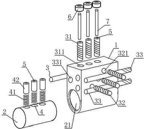
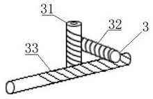
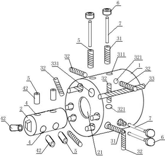
[0021] A keyless lock cylinder such as figure 1 , 2 , 3, including a lock case 1, a lock cylinder 2, and an unlocking assembly 3; the lock case 1 is provided with a cylinder hole 21, and the lock cylinder 2 is rotatably arranged in the cylinder hole 21; the lock case 1 is provided with a round hole 311 , the transmission hole 321, the unlocking hole 331, one end of the round hole 311 is connected with the lock cylinder hole 21, the other end runs through the lock housing 1, the transmission hole 321 is connected with the round hole 311, the unlocking hole 331 runs through the lock body and connects with the transmission hole 321 The unlocking assembly 3 includes a lock case pin 31, a transmission rod 32, and an unlocking rod 33, the lock case pin 31 is arranged in the circular hole 311, the transmission rod 32 is arranged in the transmission hole 321, and the unlocking rod 33 is arranged in the unlocking hole 331; The shell pin 31, the transmission rod 32, and the unlocking r...

Embodiment 2

[0028] As the preferred scheme of embodiment 1, such as figure 1 , 2 , 3, the transmission hole 321 is vertically connected to the circular hole 311; the unlocking hole 331 runs through the lock housing 1 and is vertically connected to the transmission hole 321.

[0029] The transmission hole 321 and the lock hole 21 are straight lines in different planes, and the angle between the transmission hole 321 and the lock hole 21 is 0-180 degrees, preferably 90 degrees, and the transmission hole 321 is connected with the round hole 311, and The included angle is from 0° to 180°, preferably 90° and vertically connected. The transmission hole 321 can also pass through the lock housing 1 and connect with the round hole 311 .

[0030] The unlocking hole 331 and the lock hole 21 are straight lines on different planes, and the angle between the unlocking hole 331 and the lock hole 21 is 0° to 90°, preferably 0°, parallel to each other, and the unlocking hole 331 and the transmission hole...

Embodiment 3

[0033] As the specific scheme of embodiment 1, such as figure 1 , 3 As shown, the number of the unlocking components 3 is at least one group, and the positions of the round hole 311, the transmission hole 321, and the unlocking hole 331 are set in one-to-one correspondence with the lock shell pin 31, the transmission rod 32, and the unlocking rod 33.

[0034] When there are multiple groups of unlocking components 3, each group of unlocking components 3 is arranged staggeredly, and the lock shell pins 31 in different unlocking components 3 adopt different lengths respectively. By setting the lock shell pins 31 of different lengths, different lock shell pins 31 The travel distances in the circular holes 311 are different, and then relative to the corresponding inner pin hole 4, the unlocking lever 33 needs to be rotated by different angles to control the stroke of each individual lock shell pin 31, thereby realizing a single lock. When the shell pin 31 is inserted into the corr...


PUM


Abstract

The invention discloses a keyless lock cylinder comprising a lock shell, a lock liner and an unlocking assembly. The lock shell is provided with a lock liner hole, and the lock liner is rotatably arranged in the lock liner hole; the lock shell is provided with a round hole, a transmission hole and an unlocking hole, one end of the round hole is connected with the lock liner hole, the other end ofthe round hole penetrates through the lock shell, the transmission hole is connected with the round hole, and the unlocking hole penetrates through the lock shell and is connected with the transmission hole; the unlocking assembly comprises a lock shell marble, a transmission rod and an unlocking rod, the lock shell marble is arranged in the circular hole, the transmission rod is arranged in the transmission hole, the unlocking rod is arranged in the unlocking hole, the lock shell marble is meshed with one end of the transmission rod, and the other end of the transmission rod is meshed with the unlocking rod; and the lock core is provided with an inner marble hole, and the inner marble hole corresponds to the round hole in position and has the same diameter. The keyless lock cylinder has the following beneficial technical effects that the unlocking rod is used for replacing a key and a lock hole, the anti-theft effect is better, the situation that the lock hole is blocked is avoided, and the problem that the key is prone to damage and lose is solved correspondingly as the key is cancelled.

Description

technical field [0001] The invention relates to a lock core, in particular to a keyless lock core. Background technique [0002] Existing mechanical locks are generally pin locks and shrapnel locks; the principle of pin locks is to use a plurality of cylindrical parts of different heights called lock springs, pins or beads to lock the lock cylinder. When the correct key is put in, each lock will The spring is pushed to the same height, and the space between the upper pin and the lower pin is aligned with the lock cylinder in a straight line. When the space between the pins is aligned with the rotation line, the lock cylinder can be rotated and the lock is also opened; the shrapnel lock is through The shrapnel on the lock cylinder locks the lock cylinder; both of these two locks have a low mutual opening rate and a certain anti-theft ability, but since these two locks are driven by the key to rotate the lock cylinder, the violent knob is used to lock the cylinder. Destroy th...

Claims


Application Information

Patent Timeline
Patent Type & Authority Applications(China)
IPC IPC(8): E05B27/00E05B15/00E05B15/14E05B9/04E05B37/00
CPCE05B27/0003E05B27/0007E05B27/0014E05B27/0017E05B27/0035E05B27/0057E05B37/00
Inventor 雷敬汉雷关东
Owner 雷关东
Why Eureka
Try Eureka