A weighbridge weighing support structure and using method thereof
What is AI technical title?
AI technical title is built by PatSnap AI team. It summarizes the technical point description of the patent document.
A weighbridge, weighing technology, applied in the direction of weighing oscillation damping, detailed information of weighing equipment, weighing, etc., can solve the problems of large impact force, damage to the load cell, affecting the weighing accuracy of the weighbridge, etc., to improve the use of Longevity, reduced momentary stress, excellent cushioning effect
Active Publication Date: 2022-05-06
NANJING LINGQUE INTELLIGENT MFG CO LTD
View PDF11 Cites 0 Cited by
Summary
Abstract
Description
Claims
Application Information
AI Technical Summary
This helps you quickly interpret patents by identifying the three key elements:
Problems solved by technology
Method used
Benefits of technology
Problems solved by technology
[0004] The main purpose of the present invention is to provide a weighbridge weighing support structure, which can effectively solve the problem that the existing weighbridge weighing support structure in the background technology does not have the buffer protection function. When the weight moves to the upper part of the weighbridge platform, It will bring instantaneous pressure to the weighbridge, without suitable buffer measures, it will have a great impact on the service life of the load cell, thereby reducing the service life of the entire weighbridge, and the safety is poor; secondly, it does not have anti-collision function, due to the weight When the object moves to the upper part of the weighbridge, it will cause the weighbridge to shake, and the gap between the weighbridge and the foundation pit is large, which makes the shake of the weighbridge very large. If the shake is too large, the impact force will be greater, thus It will produce more vibration, which will affect the weighing accuracy of the platform scale, and will also affect the service life of the platform scale; in addition, it does not have the function of vertical limit, because the platform scale mainly uses the heavy sensor between the platform scale and its feet when it is heavy Weighing, but the range of motion of the load cell is limited. If it exceeds the range of motion, the load cell will be damaged, which is not conducive to the technical problems of use.
Method used
Image
Click on the blue label to locate the original text in one second.
Reading with bidirectional positioning of images and text.
Examples
Embodiment Construction
[0028] In order to make the technical means, creative features, goals and effects achieved by the present invention easy to understand, the present invention will be further described below in conjunction with specific embodiments.
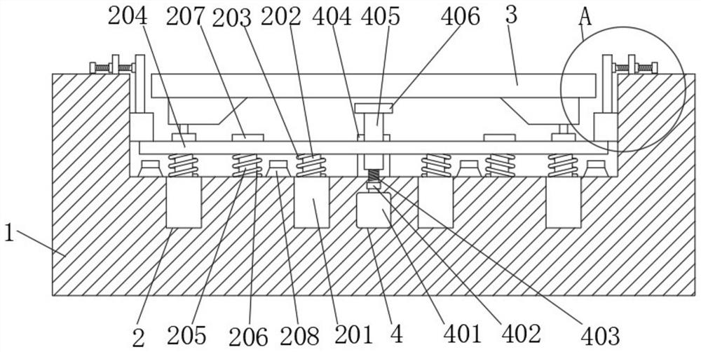
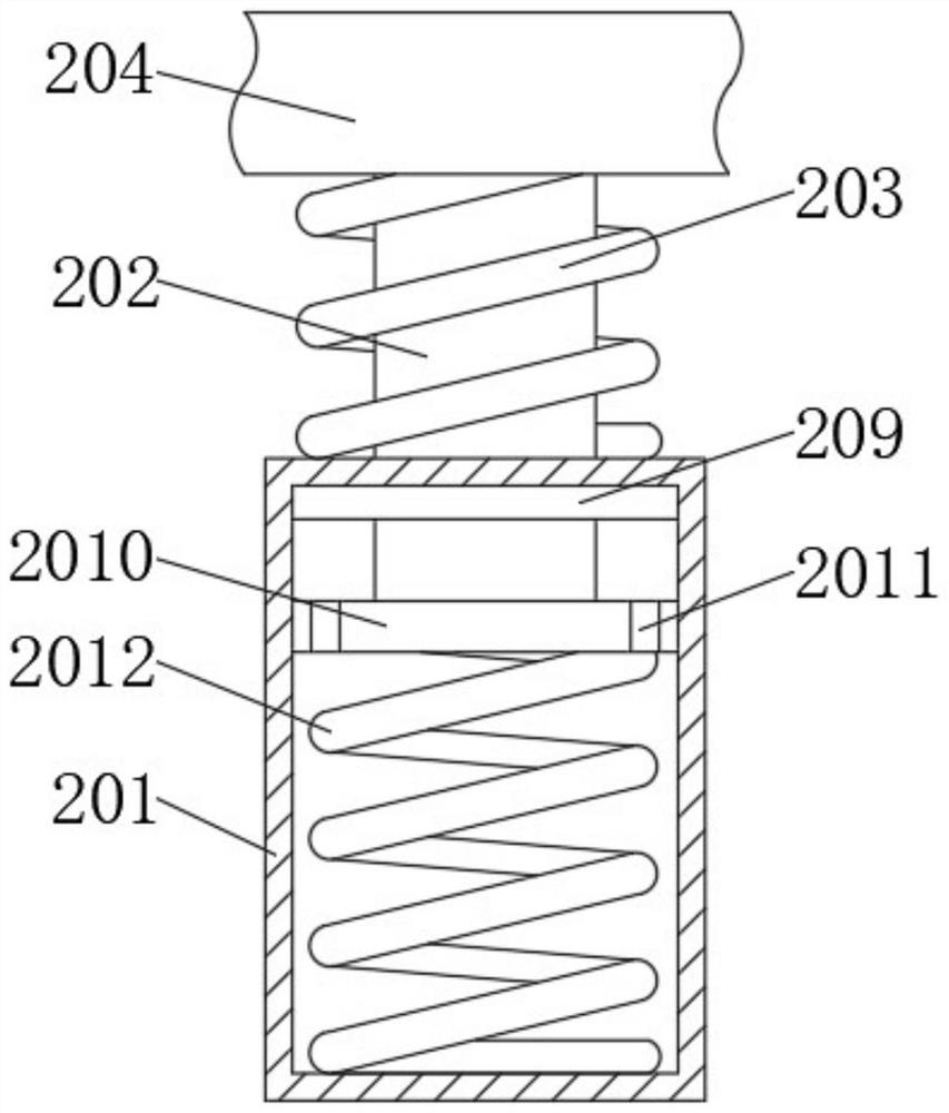
[0029] Such as Figure 1-5 As shown, a weighbridge weighing support structure includes a foundation pit 1 and a weighbridge 3, a buffer protection mechanism 2 is provided between the foundation pit 1 and the weighbridge 3, and the buffer protection mechanism 2 includes a buffer seat 201, a buffer rod 202, a second One spring 203, buffer plate 204, guide rod 205, second spring 206, stop block 207, stop seat 208, sealing ring 209, piston 2010, flow hole 2011, the third spring 2012, the side of foundation pit 1 and A horizontal anti-collision mechanism 5 is provided between the weighbridges 3, and the horizontal anti-collision mechanism 5 includes a sliding seat 501, an anti-collision plate 502, a screw seat 503, a screw rod 504, a connecting sleeve ...
PUM
Abstract
The invention discloses a weighing support structure of a weighbridge and a method of use thereof, comprising a box body of a medical instrument, a foundation pit and a weighbridge, a buffer protection mechanism is arranged between the foundation pit and the weighbridge, and the buffer protection mechanism includes Buffer seat, buffer rod, first spring, buffer plate, guide rod, second spring, limit block, limit seat, sealing ring, piston, flow hole, third spring, the horizontal anti-collision mechanism includes a sliding seat , Anti-collision plate, screw seat, screw rod, connecting sleeve and lock nut. The weighing support structure of the weighbridge according to the present invention can play an excellent buffering effect and greatly improve the service life of the whole weighbridge. Secondly, it can conveniently adjust the shaking space of the weighbridge, reduce the shaking range of the weighbridge, and increase the scale of the weighbridge. In addition, it has a good vertical limit effect to avoid damage to the load cell caused by the range of motion exceeding the range of motion of the load cell.
Description
technical field [0001] The invention relates to the field of weighbridges, in particular to a weighing support structure of a weighbridge, and more particularly to a weighing support structure of a weighbridge and a use method thereof. Background technique [0002] The weighbridge is a device used to weigh medium and large objects. It is usually used in factories, farms, construction sites and other places to facilitate people to understand the weight of medium and large objects. There are two ways to install the weighbridge, one is to place it directly In the name of the place, slopes need to be set at both ends of the weighbridge. The construction is simple, but it takes up a lot of space. The other is to open a foundation pit on the ground and place the weighbridge inside the foundation pit. The construction is troublesome, but the occupied area is small. The installation method of the foundation pit , the entire foundation pit is equivalent to the manufacture of a weighb...
Claims
Application Information
Patent Timeline
Application Date:The date an application was filed.
Publication Date:The date a patent or application was officially published.
First Publication Date:The earliest publication date of a patent with the same application number.
Issue Date:Publication date of the patent grant document.
PCT Entry Date:The Entry date of PCT National Phase.
Estimated Expiry Date:The statutory expiry date of a patent right according to the Patent Law, and it is the longest term of protection that the patent right can achieve without the termination of the patent right due to other reasons(Term extension factor has been taken into account ).
Invalid Date:Actual expiry date is based on effective date or publication date of legal transaction data of invalid patent.

