Vehicle Air Suspension System

A technology for air suspension and vehicles, which is applied to suspensions, elastic suspensions, vehicle components, etc. It can solve the problems of excessive instantaneous impact of air springs, high pressure of air springs, and complicated arrangement, so as to prevent failure and extend service life Lifespan, the effect of buffering momentary pressure

Active Publication Date: 2020-07-28
ZHEJIANG KELI VEHICLE CONTROL SYST
View PDF1 Cites 0 Cited by
  • Summary
  • Abstract
  • Description
  • Claims
  • Application Information

AI Technical Summary

Problems solved by technology

The main components of the air suspension system are the air spring assembly, the height control valve, and the shock absorber. They are installed in different positions, the arrangement is complicated, the installation operation is inconvenient, and the instantaneous impact in the air spring is too large.
[0003] In the prior art, the patent name of patent No. CN201721799390.9 is a bus chassis assembly with an air suspension system, which can keep the bus better in handling and stability under different road conditions, but the air spring is still affected. The problem of excessive instantaneous pressure and failure

Method used


Image

  • Vehicle Air Suspension System
  • Vehicle Air Suspension System
  • Vehicle Air Suspension System

Examples


Embodiment 1

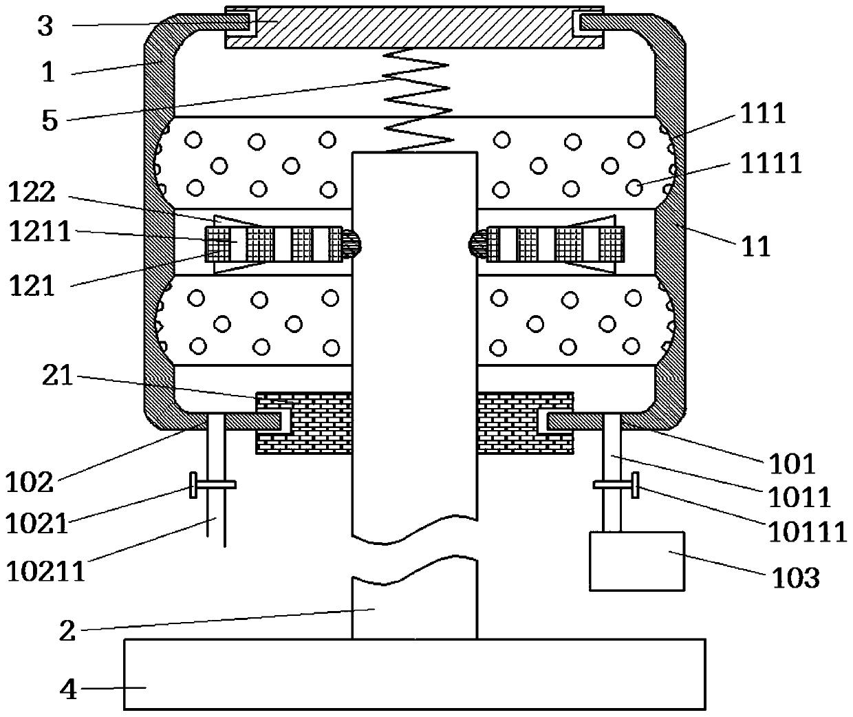
[0017] The air suspension system for vehicles, as shown in the figure, includes a shock absorber 2 and an air spring 1, and the outer wall of the shock absorber 2 is fixed with a shock absorber 21, and also includes an upper connection plate 3 and a lower connection plate 4, the upper connection The plate 3 is located above the shock absorbing rod 2, the lower connecting plate 4 is fixed on the lower end of the shock absorbing rod 2, the air spring 1 is sleeved on the upper end of the shock absorbing rod 2, the upper end of the air spring 1 is fixedly connected with the upper connecting plate 3, and the air spring The lower end of 1 is fixed on the shock absorbing ring 21, the air spring 1 is sealed and connected with the upper connecting plate 3 and the shock absorbing ring 21, and the upper and lower ends of the air spring 1 are provided with sealing rings and are respectively connected to the upper connecting plate through the sealing rings. 3 is connected with shock absorbi...

Embodiment 2

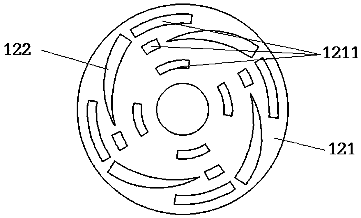
[0022] The same as Embodiment 1, the difference is that the air spring 1 includes a spring outer bag 11 and an air guiding device 12 installed in the spring outer bag 11, and also includes a shock-absorbing coil spring 5, which is located in the spring outer bag 11 Inside, the upper and lower ends of the shock-absorbing coil spring 5 are respectively pressed against the lower surface of the upper connecting plate 3 and the upper surface of the shock-absorbing rod 2; , the annular mounting plate 121 is installed on the outer wall of the upper end of the shock absorbing rod 2 and can be rotated on the axis of the shock absorbing rod 2 through the bearing. There is a gap of 20 mm between the annular mounting plate 121 and the inner wall of the spring outer bag 11. The mounting plate 121 is provided with a plurality of guide holes 1211, and the upper surface and the lower surface of the annular mounting plate 121 are provided with a plurality of arc-shaped plates 122, and the arc-s...

Embodiment 3

[0024] Same as Embodiment 2, the difference is that a gap of 27 mm is provided between the annular mounting plate 121 and the inner wall of the spring outer bag 11, and the height of the protrusion at the outer end of the arc-shaped plate 122 is 1.7 times the height of the protrusion at the inner end of the arc-shaped plate 122 .


PUM


Abstract

The invention relates to the field of vehicles and discloses an automotive air suspension system. The automotive air suspension system comprises a damping rod (2) and an air spring (1); a damping ring(21) is fixedly arranged on the outer wall of the damping rod (2); the automotive air suspension system also comprises an upper connecting plate (3) and a lower connecting plate (4); the air spring (1) is hermetically connected with the upper connecting plate (3) and the damping ring (21); the air spring (1) comprises a spring outer bag (11) and an air flow guide device (12); the automotive air suspension system also comprises a damping spiral spring (5); the air flow guide device (12) comprises an annular mounting plate (121) fixed at the upper end of the damping rod (2); a plurality of flowguide holes (1211) are formed in the annular mounting plate (121); and a plurality of arc-shaped plates (122) are arranged on the annular mounting plate (121). Through the air flow guide device arranged in the air spring, the instantaneous pressure of the air spring is effectively buffered, failure of the air spring is avoided and the service life of products is prolonged.

Description

technical field [0001] The invention relates to the field of vehicles, in particular to an air suspension system for vehicles. Background technique [0002] The traditional car suspension system uses steel springs with linear characteristics. When the car is unloaded, the car body rises very high, and when it is heavily loaded, the car body is pressed very low. The height of the suspension system changes with the change of the load. The suspension system of modern cars mostly adopts the air suspension system. According to the different road conditions and the signal of the distance sensor, the driving computer will judge the change of the height of the vehicle body, and then control the air compressor and the exhaust valve to make the air spring automatically compress or extend, thereby Reduce or increase the ground clearance of the chassis to increase the stability of the high-speed body or the passability of complex road conditions. The main components of the air suspensi...

Claims


Application Information

Patent Timeline
Patent Type & Authority Patents(China)
IPC IPC(8): B60G17/0165B60G17/052
Inventor 马靖林勇伟
Owner ZHEJIANG KELI VEHICLE CONTROL SYST
Why Eureka
Try Eureka