Common bifocal optical antenna system

An optical antenna and dual focus technology, applied in the field of optical remote sensing communication, can solve the problems of large volume, small field of view, inability to track and capture costs, etc., and achieve the effects of many communication nodes, large dynamic tracking range, and easy miniaturization and light weight.

Inactive Publication Date: 2020-11-27
BEIJING INST OF SPACECRAFT SYST ENG
View PDF5 Cites 0 Cited by
  • Summary
  • Abstract
  • Description
  • Claims
  • Application Information

AI Technical Summary

Problems solved by technology

[0005] The problem solved by the structure of the present invention is: in order to overcome the problems of small field of view, large volume, inability to track and capture and high cost existing in the existing one-to-many laser communication equipment antenna device

Method used


Image

  • Common bifocal optical antenna system
  • Common bifocal optical antenna system
  • Common bifocal optical antenna system

Examples


Embodiment Construction

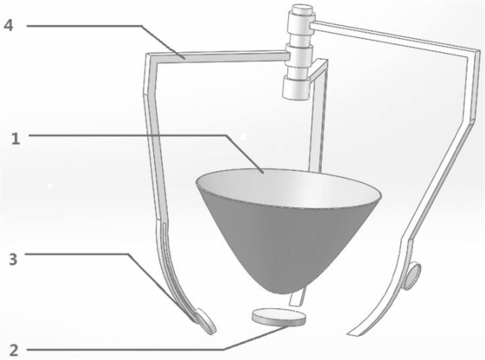
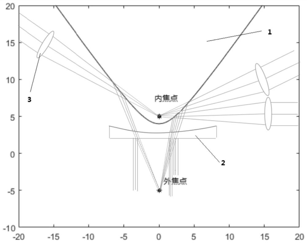
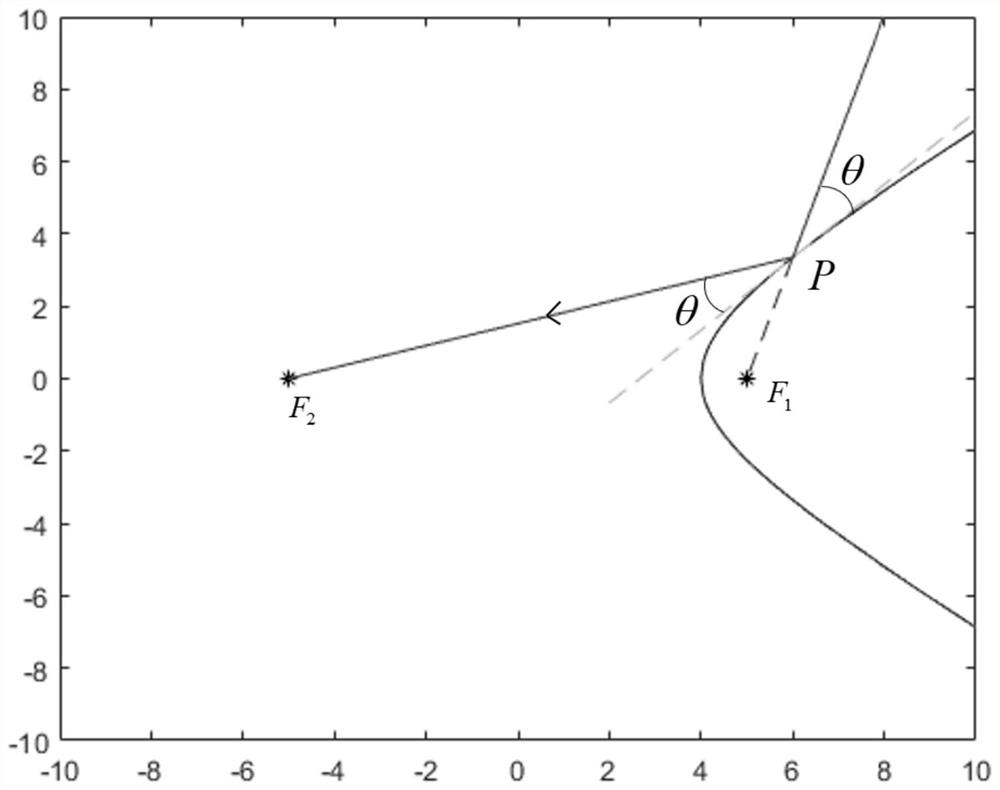
[0023] like figure 1 As shown, a shared bifocal optical antenna system consists of a rotating double-leaf hyperboloid reflector, a diverging lens unit, a converging lens unit and a control system. The system structure is: the center is the double-leaf hyperboloid reflector 1, and the double-leaf hyperboloid reflector 1 has two focal points, inner and outer; The focus of is outer focus. Multiple groups of converging lens units 3 are distributed on the outside of the rotating hyperboloid reflector, and the focus of each group of converging lens units 3 coincides with the inner focus of the double-leaf hyperboloid reflector 1, that is, they share the inner focus. The outer focal points of the leaf hyperboloid reflectors 1 coincide, that is, share the outer focal points. The control system consists of a rotating arm, a rotating shaft, an arc-shaped slide rail and related control structures. The rotating arm can move in a circle around the rotation axis, and the converging lens ...


PUM


Abstract

The invention relates to a common bifocal optical antenna system. A rotary double-blade hyperboloid reflector is arranged in the center of the system and is provided with an inner focal point and an outer focal point, the focal point located in the rotary hyperboloid reflector is the inner focal point, and the focal point located outside the rotary hyperboloid reflector is the outer focal point. The convergent lens units are distributed on the outer side of the rotating hyperboloid reflector, the focal point of each convergent lens unit coincides with the inner focal point of the double-bladehyperboloid reflector, namely the inner focal point is shared, and the focal point of a divergent lens unit coincides with the outer focal point of the double-blade hyperboloid reflector, namely the outer focal point is shared. Each convergent lens unit is located at any position of the space spherical surface with the inner focal point of the rotating hyperbolic reflector as the sphere center andthe focal length of each convergent lens unit as the radius, and the position change of the convex lens unit on the respective space spherical surface is adjusted by the control system. The diverginglens unit is located below the double-blade hyperboloid reflector, and the optical axis of the diverging lens unit coincides with the rotating axis of the double-blade hyperboloid reflector.

Description

technical field [0001] The invention relates to a shared bifocal optical antenna system, which belongs to the technical field of optical remote sensing communication. Background technique [0002] As the amount of information transmission increases exponentially, users will have higher and higher demands on data transmission capabilities in the future. Compared with radio frequency communication, laser communication has many obvious advantages, including fast data transmission, low energy loss, large bandwidth, small size of communication terminal, and good anti-interference and confidentiality, etc., showing an ascendant development trend. The use of laser communication technology can realize the "live broadcast" real-time transmission of the situation awareness of the enemy and the enemy on the battlefield, the state of natural disasters, etc. It is especially suitable for unmanned platforms, aircraft, satellites and other communication platforms with limited load capacit...

Claims


Application Information

Patent Timeline
Patent Type & Authority Applications(China)
IPC IPC(8): G02B17/08G02B7/02G02B3/00G02B5/10
CPCG02B3/00G02B5/10G02B7/023G02B17/0864
Inventor 张涛杨冬赵文汤海涛李贞李婷卢铮汪大宝梅潇李玉高倪辰刘彬姜宇王志斌陈彦杰
Owner BEIJING INST OF SPACECRAFT SYST ENG
Why Eureka
Try Eureka