Converter valve trigger architecture for realizing live-line fault processing

A live treatment and converter valve technology, applied in the direction of power transmission AC network, output power conversion device, electrical components, etc., can solve the problems of inaccessibility, trigger pulse interruption, etc., to improve reliability, improve safety, reduce The effect of the risk of forced outage

Active Publication Date: 2020-11-27
GUANGZHOU BUREAU CSG EHV POWER TRANSMISSION
View PDF9 Cites 0 Cited by
  • Summary
  • Abstract
  • Description
  • Claims
  • Application Information

AI Technical Summary

Problems solved by technology

[0003] The problem with this architecture is that there is only one trigger fiber from the valve-based electronic device to the thyristor electronic board. When the fiber fails, the transmission of the trigger pulse will be interrupted; at the same time, since the converter valve cannot be approached when it is electrified, it can only wait Replace the faulty optical fiber when the power is off; during the waiting period, the corresponding valves will quit running because they cannot receive the trigger signal, and when the valves that cannot be triggered in the (Ultra) HVDC transmission system reach a certain number, they will be shut down. emergency shutdown

Method used


Image

  • Converter valve trigger architecture for realizing live-line fault processing

Examples


Embodiment Construction

[0016] The present invention will be further described in detail below with reference to the accompanying drawings and embodiments.

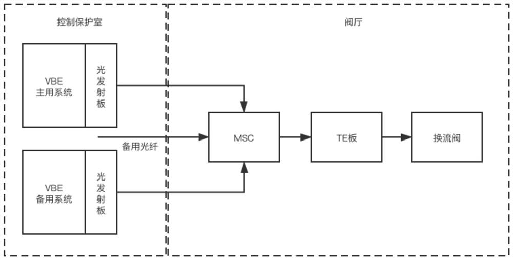
[0017] like figure 1 As shown in the figure, the present invention is a converter valve triggering structure for realizing live processing of faults, including a thyristor electronic board connected to the converter valve signal, and the thyristor electronic board is located in the valve hall; it also includes a VBE main system and a VBE backup system, the VBE The main system and the VBE backup system are located in the control protection room, and the VBE main system and the VBE backup system are respectively installed with a first light emitting board and a second light emitting board.

[0018] The thyristor electronic board is connected with the MSC module of the optical fiber coupler through the optical fiber signal, the entrance of the MSC module is respectively preset with the main optical fiber, the standby optical fiber and the preset op...


PUM


Abstract

The invention relates to a converter valve trigger architecture for realizing live-line fault processing. The architecture comprises a thyristor electronic board in signal connection with a convertervalve, and the thyristor electronic board is located in a valve hall; and the architecture further comprises a VBE main system and a VBE standby system. The VBE main system and the VBE standby systemare located in a control protection chamber. The VBE main system and the VBE standby system are respectively provided with a first light-emitting plate and a second light-emitting plate; the thyristorelectronic board is connected with an MSC module of an optical fiber coupler, a main optical fiber, a standby optical fiber and a preset optical fiber are preset at an inlet of the MSC module, the main optical fiber is connected with the first light-emitting board, the standby optical fiber is connected with the second light-emitting board, and the end, away from the MSC module, of the preset optical fiber is located in the control protection chamber. By adopting the technical scheme, the operation reliability of the converter valve is improved. The redundancy of trigger pulses simultaneouslysent by the two systems can be recovered, and the safety of maintenance operation is improved at the same time.

Description

technical field [0001] The present invention relates to the technical field of converter valves in power systems, in particular to a converter valve triggering structure for realizing live fault handling. Background technique [0002] In the current (Ultra) HVDC system power transmission system, the valve base electronic equipment (VBE) sends out the pulse to trigger the converter valve, and sends the trigger pulse to the thyristor electronic board, and then the thyristor electronic board realizes the Triggering of the converter valve. [0003] The problem with this architecture is that there is only one trigger optical fiber from the valve base electronic device to the thyristor electronic board. When the optical fiber fails, the transmission of the trigger pulse will be interrupted; at the same time, since the converter valve cannot be approached under the condition of electrification, it can only wait The faulty optical fiber is replaced at the time of power failure; dur...

Claims


Application Information

Patent Timeline
Patent Type & Authority Applications(China)
IPC IPC(8): H02M1/06H02J3/36
CPCH02J3/36H02M1/06Y02E60/60
Inventor 庞准张鹏周文瑞王晨涛谢桂泉梁家豪林启奋杨帆王振杨建文严治勇陶敏林永宏梁梓贤
Owner GUANGZHOU BUREAU CSG EHV POWER TRANSMISSION
Why Eureka
Try Eureka