Differential line wiring structure and differential line wiring structure generation method

A wiring structure and differential line technology, which is applied in the direction of printed circuit making wiring diagrams, printed circuits, circuit electrical components, etc., can solve the problems of high density, compressed differential line routing space, small size, etc., to improve transmission quality, Improve reliability and avoid the effect of impedance discontinuity

Inactive Publication Date: 2020-11-27
北京浪潮数据技术有限公司
View PDF7 Cites 0 Cited by
  • Summary
  • Abstract
  • Description
  • Claims
  • Application Information

AI Technical Summary

Problems solved by technology

[0002] With the increasing demand for high-speed and high-density storage servers, high-speed connectors and differential lines are often used on PCBs (Printed Circuit Boards). However, the current high-speed connectors are small in size and high in density, which reduces the routing of differential lines line space, presenting challenges for impedance control of differential lines; see figure 1 , is a typical wiring diagram of the differential line in the local area of ​​the connector in the existing scheme; through figure 1 It can be seen that in order to ensure the impedance design requirements, it is necessary to set the width of the differential line to W and the line pitch to P; at the same time, the antipad (anti-pad) area of ​​the differential via hole of the connector is hollowed out; due to the space in the connector area Limitation, when the differential line enters the connector area from the normal wiring area, the crosstalk will increase because the differential line is too close to the via hole, and the differential line will cross the elliptical hollow area, resulting in impedance discontinuity

Method used


Image

  • Differential line wiring structure and differential line wiring structure generation method
  • Differential line wiring structure and differential line wiring structure generation method
  • Differential line wiring structure and differential line wiring structure generation method

Examples


Embodiment Construction

[0029] The following will clearly and completely describe the technical solutions in the embodiments of the present invention with reference to the accompanying drawings in the embodiments of the present invention. Obviously, the described embodiments are only some, not all, embodiments of the present invention. Based on the embodiments of the present invention, all other embodiments obtained by persons of ordinary skill in the art without creative efforts fall within the protection scope of the present invention.

[0030] The embodiment of the present invention discloses a differential line wiring structure and a method for generating the differential line wiring structure, so as to ensure continuous impedance of the differential line, avoid crosstalk, and prevent the differential line from crossing the anti-pad.

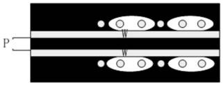
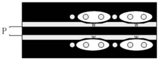
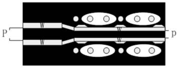
[0031] see figure 2 , a differential line wiring structure provided by an embodiment of the present invention, the differential line wiring structure includes two...


PUM


Abstract

The invention discloses a differential line wiring structure. The differential line wiring structure comprises two differential lines which are distributed in parallel, and an avoiding groove used foravoiding a connector anti-bonding pad is formed in the portion, corresponding to the connector anti-bonding pad, of each differential line. It can be known that the differential lines in the differential line wiring structure are provided with receding grooves, the avoiding grooves are formed in the portion, close to the connector anti-bonding pad, of the differential lines, so that the connectoranti-bonding pads are avoided through the avoiding grooves, crosstalk increase caused by the fact that the differential lines are too close to a via hole is avoided, meanwhile, impedance discontinuity caused by the fact that the differential lines cross the connector anti-bonding pads is avoided, the signal transmission quality is improved, and the product reliability is improved. The invention further discloses a generation method of the differential line wiring structure of the connector area. The above technical effects can also be achieved.

Description

technical field [0001] The present invention relates to the technical field of differential wiring, and more specifically, to a differential wiring structure and a method for generating the differential wiring structure. Background technique [0002] With the increasing demand for high-speed and high-density storage servers, high-speed connectors and differential lines are often used on PCBs (Printed Circuit Boards). However, the current high-speed connectors are small in size and high in density, which reduces the routing of differential lines line space, presenting challenges for impedance control of differential lines; see figure 1 , is a typical wiring diagram of the differential line in the local area of ​​the connector in the existing scheme; through figure 1 It can be seen that in order to ensure the impedance design requirements, it is necessary to set the width of the differential line to W and the line pitch to P; at the same time, the antipad (anti-pad) area of ​...

Claims


Application Information

Patent Timeline
Patent Type & Authority Applications(China)
IPC IPC(8): H05K1/02H05K3/00
CPCH05K1/0228H05K1/025H05K3/0002H05K2201/0776H05K2201/07H05K2203/0502
Inventor 梁磊秦清松
Owner 北京浪潮数据技术有限公司
Why Eureka
Try Eureka