A compound pest trap for granary
A compound trap technology, which is applied in the application, device for capturing or killing insects, animal husbandry, etc., can solve the problems of reduced trapping efficiency, achieve high trapping efficiency, avoid flying insects from escaping, and prevent escaping
- Summary
- Abstract
- Description
- Claims
- Application Information
AI Technical Summary
Problems solved by technology
Method used
Image

Examples
Embodiment 1
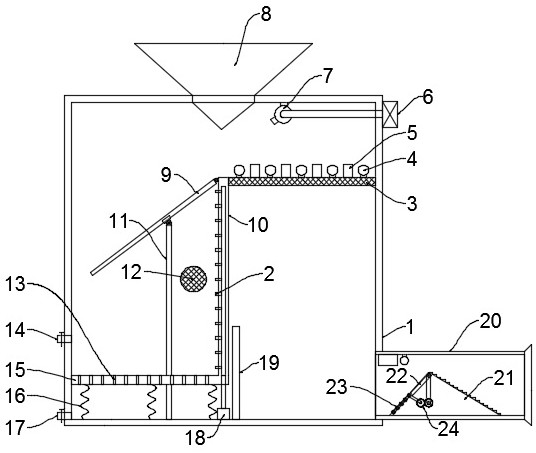
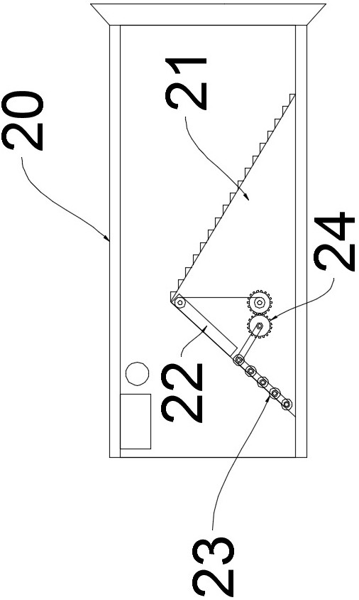
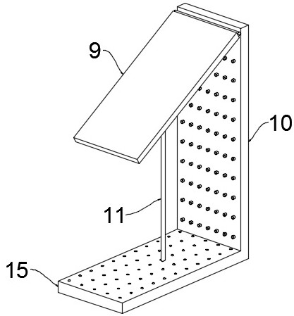
[0024] see Figure 1~3 , in an embodiment of the present invention, a compound pest trap for granaries, comprising a box body 1, an insect trap light 4 disposed in the box body 1, and a box 5 containing an insect attractant, the box body 1 is equipped with a box The door is convenient for cleaning pests, and also includes a flying insect trapping unit. The flying insect trapping unit includes a mounting plate 10, a support plate 15, a compression spring 16, a fixed rod 11, a movable plate 9, a partition 19 and a hard pipe 7, and the box The middle part of the body 1 cavity is provided with a vertical mounting plate 10, the bottom end of the mounting plate 10 is fixedly connected with one end of the support plate 15, and the other end of the support plate 15 is in contact with the side wall of the cavity of the box body 1, the mounting plate 10 and the support plate 15 The longitudinal length is the same as the length of the inner cavity of the box body 1, and the support plate...
Embodiment 2
[0027] see Figure 4 The difference between this embodiment of the present invention and Embodiment 1 is that it also includes an electric shock unit, the electric shock unit includes a support plate, a power grid 28 and a driving mechanism for driving the support plate to move up and down, and the lower surface of the support plate is fixedly installed with A plurality of grids 28, the grid 28 is electrically connected to the external power supply, one end of the support plate is slidingly connected to the inner wall of the box body 1, and a buzzer 25 is installed on the lower surface of the support plate. The driving mechanism includes a motor, a turntable 26 and a connecting rod 27, and the motor is fixed. Installed on the box body 1 and above the support plate, a turntable 26 is fixedly installed on the output shaft of the motor, the outer ring of the end face of the turntable 26 is hinged with one end of the connecting rod 27, and the other end of the connecting rod 27 is ...
PUM
 Abstract
Description
Claims
Application Information
 - R&D
- Intellectual Property
- Life Sciences
- Materials
- Tech Scout
- Unparalleled Data Quality
- Higher Quality Content
- 60% Fewer Hallucinations
Browse by: Latest US Patents, China's latest patents, Technical Efficacy Thesaurus, Application Domain, Technology Topic, Popular Technical Reports.
© 2025 PatSnap. All rights reserved.Legal|Privacy policy|Modern Slavery Act Transparency Statement|Sitemap|About US| Contact US: help@patsnap.com