A kind of drawing arm used for profile stretch bending

A profile and material arm technology, which is applied in the field of profile drawing arm, can solve problems such as low work efficiency, high labor cost, and adjustment of mandrel insertion position, so as to improve efficiency, improve practicability, and improve stretch forming quality effect

Active Publication Date: 2021-02-05
GUANGDONG G CLEF BENDING TECH CO LTD
View PDF8 Cites 0 Cited by
  • Summary
  • Abstract
  • Description
  • Claims
  • Application Information

AI Technical Summary

Problems solved by technology

Most of the existing equipment requires manual core threading, which requires high labor costs and extremely low work efficiency
In order to improve the processing efficiency, a core-piercing and core-pulling mechanism is also added to the stretch bending equipment. However, most of the existing core-piercing and core-pulling mechanisms are separately added to the drawing arm, and the insertion position of the mandrel cannot be adjusted according to the position of the profile. Resulting in low practicality and versatility

Method used


Image

  • A kind of drawing arm used for profile stretch bending
  • A kind of drawing arm used for profile stretch bending
  • A kind of drawing arm used for profile stretch bending

Examples


Embodiment 1

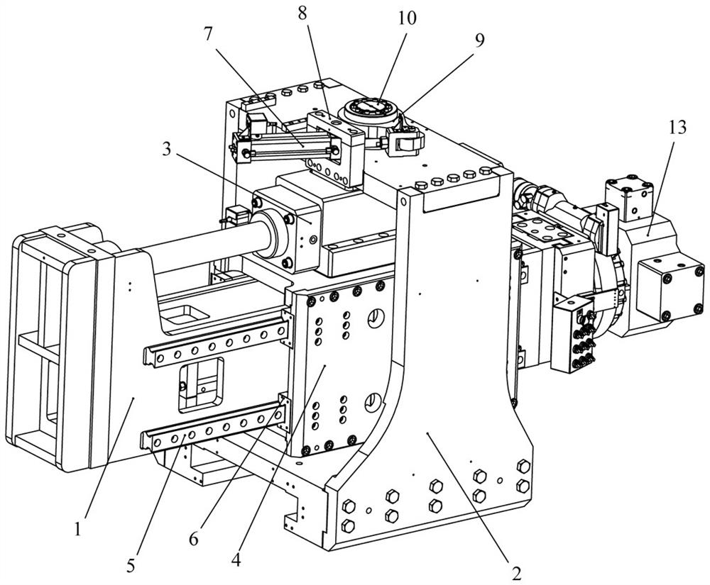
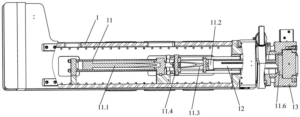
[0046] like Figure 1 to Figure 10 As shown, the drawing arm used for profile stretch bending in the present invention includes a chuck 13, an arm body 1, a core-piercing and core-pulling mechanism 11, a mandrel 12, an outer frame 2, and a stretching cylinder for driving the arm body 1 to telescopically move 3. The stretching oil cylinder mounting frame 4 and the rotating device for driving the arm body 1 to rotate; wherein, the arm body 1 is installed on the stretching oil cylinder mounting frame 4 and connected with the chuck 13, and the stretching oil cylinder 3 is arranged on the stretching oil cylinder The top of the oil cylinder mounting frame 4 is located above the arm body 1, and the driving end of the stretching oil cylinder 3 is connected with the end of the arm body 1 away from the chuck to realize the sliding connection between the arm body 1 and the stretching oil cylinder mounting frame 4, while the stretching oil cylinder 3 The rotation device is connected with ...

Embodiment 2

[0063] This embodiment differs from Embodiment 1 only in that: Figure 11 As shown, the mandrel of this embodiment includes a joint unit, the joint unit includes a joint part 12.8 and a mandrel rod 12.9, the joint part 12.8 is a movable detachable structure, and the joint part 12.8, the mandrel rod 12.9 and the mandrel are connected The rods 12.1 are in turn hinged and detachably connected.

[0064] The mandrel of this embodiment is suitable for the stretch bending process of only one cavity structural profile.

[0065] Other structures of this embodiment are consistent with Embodiment 1.

Embodiment 3

[0067] This embodiment differs from Embodiment 1 only in that: Figure 12 As shown, the joint part of the mandrel in this embodiment, the mandrel pull rod and the mandrel connecting rod 12.1 are connected sequentially, specifically: the joint part 1 of the joint unit 1 is hinged with the mandrel pull rod 12.2, and the joint part 2 of the joint unit 2 is connected with the mandrel rod 12.2. Mandrel tie rod two 12.5 are hinged, and mandrel tie rod one 12.2 and mandrel tie rod two 12.5 are connected with mandrel connecting rod 12.1 and are integrally structured to form a mandrel body.

[0068] Other structures of this embodiment are consistent with Embodiment 1.


PUM


Abstract

The invention provides a drawing arm for profile stretch bending, which includes a chuck, an arm body, a core-piercing and core-pulling mechanism, a mandrel, an outer frame, a stretching oil cylinder, a stretching oil cylinder mounting frame and a rotating device; the arm body wears It is installed on the mounting frame of the stretching cylinder and connected with the chuck. The stretching cylinder is set on the mounting frame of the stretching cylinder and connected with the arm body to realize the sliding connection between the arm body and the mounting frame of the stretching cylinder; the stretching cylinder is connected with the The outer frame is rotated and connected to realize the rotation of the arm body so that the arm body is aligned with the profile; the core-piercing and core-pulling mechanism includes a core-piercing cylinder, a mandrel connecting block and a mandrel transition block all arranged in the arm body; the mandrel connection One end of the block is adjustable and detachable connected with the mandrel transition block, and the other end is detachably connected with the mandrel; the mandrel transition block is connected with the core-pull cylinder. The drawing arm can not only quickly and efficiently realize the insertion of the mandrel in the profile to support the profile, but also realize the alignment with the profile, thereby improving the efficiency and practicability of the profile stretching and bending.

Description

technical field [0001] The invention relates to the technical field of profile stretch bending, and more specifically, relates to a drawing arm for profile stretch bending. Background technique [0002] Stretch bending machines are suitable for many fields in the machinery industry, mainly because many building materials need to be processed into a certain arc to achieve the overall function or beauty of the building. The stretch bending machine mainly bends metal sheets, pipes and profiles into a certain curvature by external force. The stretch bending machine is easy to operate, makes the arc of the processed profile perfect, can improve the processing accuracy and process consistency, and improve production efficiency. [0003] The drawing arm of the stretch bending machine is used to clamp and stretch the profile. Before the profile is bent, the positions of the drawing arms on both sides need to be adjusted to achieve alignment with the profile. At present, in the pro...

Claims


Application Information

Patent Timeline
Patent Type & Authority Patents(China)
IPC IPC(8): B21D11/02B21D11/22
CPCB21D11/02B21D11/22
Inventor 郑晓宏
Owner GUANGDONG G CLEF BENDING TECH CO LTD
Why Eureka
Try Eureka