Workshop safety inspection rescue robot

A rescue robot and workshop safety technology, which is applied to manipulators, motor vehicles, tracked vehicles, etc., can solve the problems of casualties, high cost of manual inspection, and high risk

Inactive Publication Date: 2020-12-01
HUNAN VOCATIONAL INST OF TECH
View PDF11 Cites 0 Cited by
  • Summary
  • Abstract
  • Description
  • Claims
  • Application Information

AI Technical Summary

Problems solved by technology

[0004] The purpose of the present invention is to provide a workshop safety inspection and rescue robot to solve the problem of the high cost and high risk of manual inspection at present, and when an accident occurs, it is necessary to manually wear protective tools and rescue tools to reach the scene. The problem of not being timely is likely to cause unnecessary casualties

Method used


Image

  • Workshop safety inspection rescue robot
  • Workshop safety inspection rescue robot
  • Workshop safety inspection rescue robot

Examples


Embodiment 1

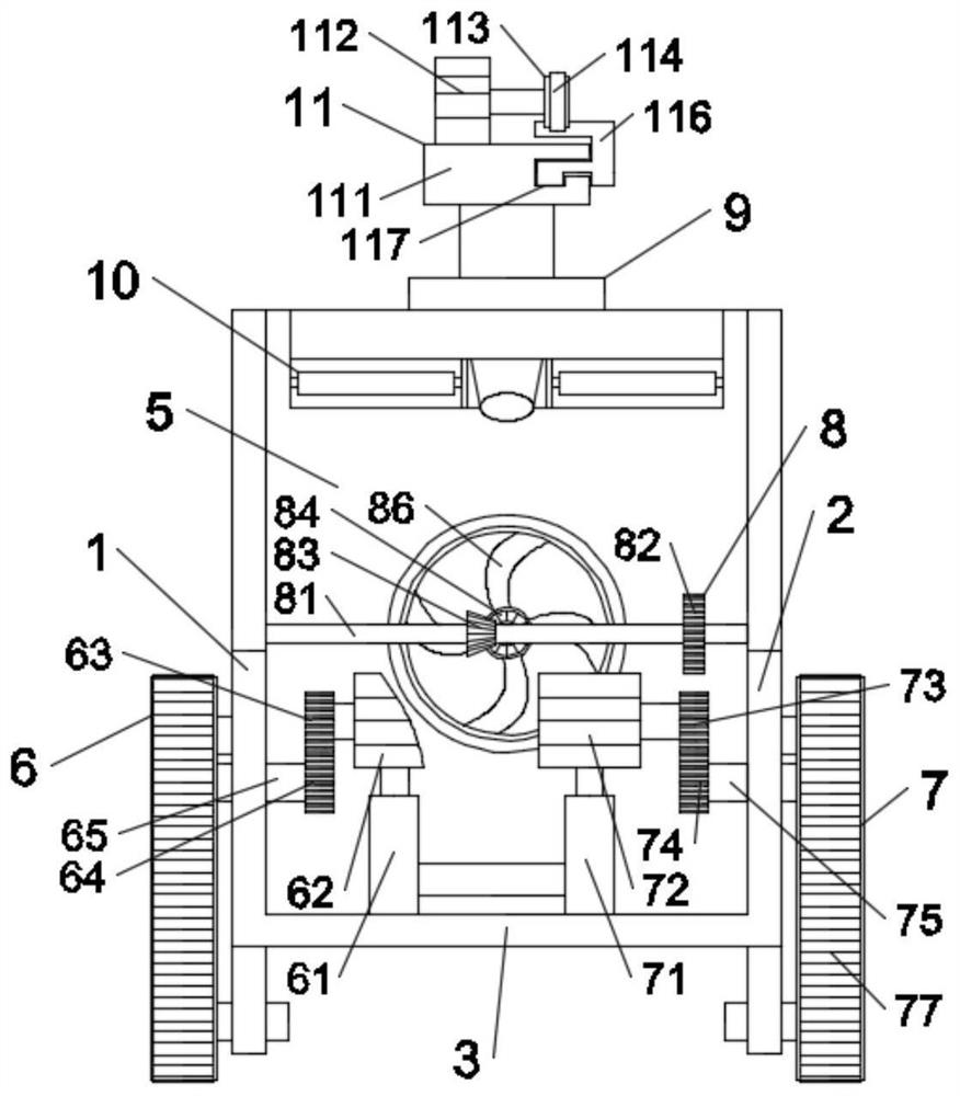
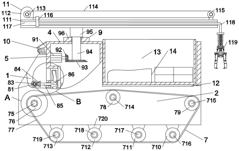
[0022] Such as Figure 1-Figure 4 As shown, in the embodiment of the present invention, a workshop safety inspection rescue robot includes a left side board 1 and a right side board 2, and a bottom board 3 and an upper board are connected between the left side board 1 and the right side board 2 4 and a vertical partition 5, the left side panel 1 and the right side panel 2 are respectively connected with a left steering device 6 and a right side steering device 7, and a fan device 8 is installed on the vertical partition 5, An inspection mechanism 10 is fixedly connected to the front of the vertical partition 5, and a rotating mechanism 9 is connected to the upper plate 4, and the rotating mechanism 9 is connected to a mechanical arm retractable mechanism 11. The upper plate 4, A transport space 12 is provided at the corresponding positions behind the left side plate 1 and the right side plate 2, and a cargo compartment 13 is housed in the transport space 12, and several differ...

Embodiment 2

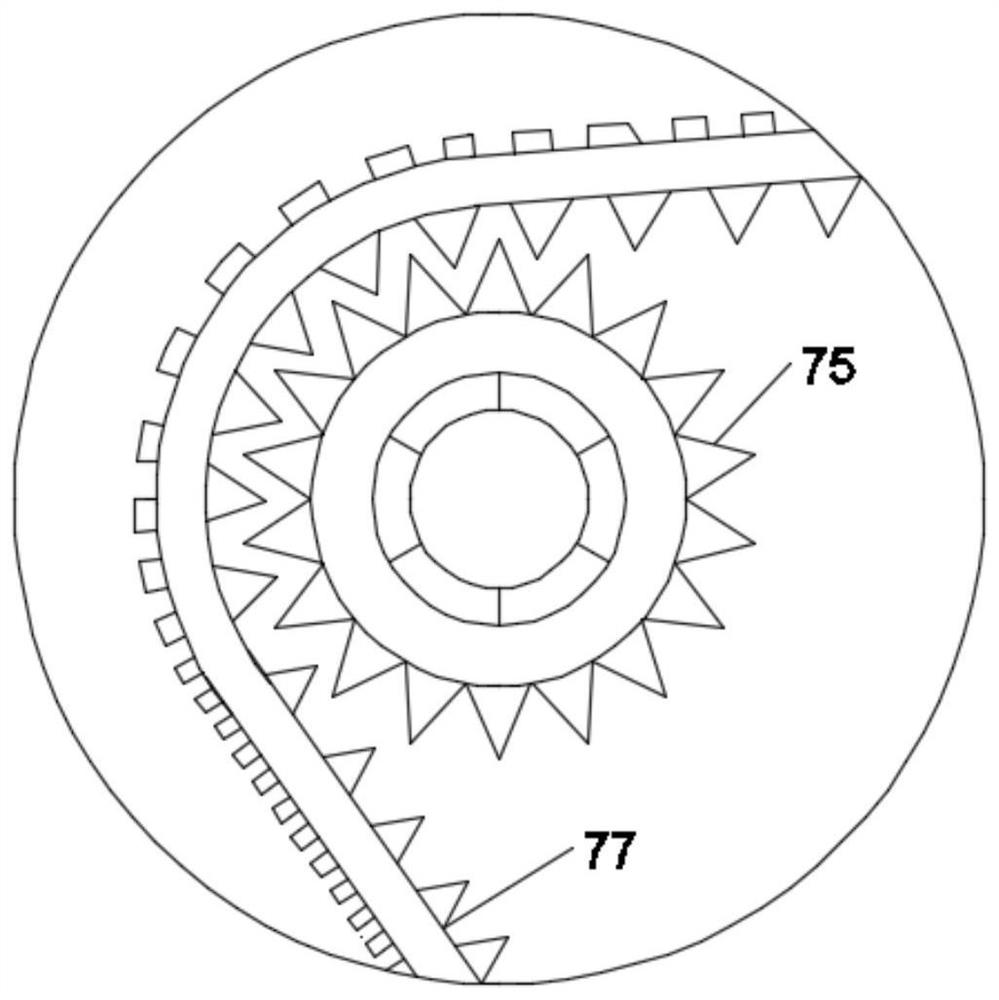
[0025] Such as Figure 1-Figure 4 As shown, in the embodiment of the present invention, the right steering device 7 includes a first telescopic member 71, the upper end of the first telescopic member 71 is fixedly connected with a first motor 72, and the first motor 72 is connected with a first Gear 73, the first gear 73 meshes with a second gear 74, the second gear 74 is connected to a first shaft 75, and one end of the first shaft 75 passing through the right side plate 2 is fixedly connected to a first sprocket 76, the first sprocket 76 is connected with the first track 77, and the first track 77 is connected with the second sprocket 78, the third sprocket 79, the fourth sprocket 710, the fifth sprocket 711, the Six sprockets 712 and the seventh sprocket 713, the second sprocket 78, the third sprocket 79, the fourth sprocket 710, the fifth sprocket 711, the sixth sprocket 712 and the seventh sprocket 713 are respectively connected There are a second shaft 714 , a third sha...

Embodiment 3

[0028] Such as Figure 1-Figure 4 As shown, in the embodiment of the present invention, the first rotating shaft 75, the second rotating shaft 714 and the third rotating shaft 715 are rotatably connected to the right side plate 2, and the second rotating shaft 714 is compared with the second rotating shaft 714 and the third rotating shaft 714. The installation position of the three rotating shafts 715 is a little higher, and the fourth rotating shaft 716, the fifth rotating shaft 717, the sixth rotating shaft 718 and the seventh rotating shaft 719 are respectively installed on four right rotating shaft seats 720 equally spaced in the horizontal direction. The right rotating shaft seat 720 is fixed on the bottom end of the right side plate 2 .

[0029]In the embodiment of the present invention, because the first crawler belt 77 is easily affected by gravity at the position of the second rotating shaft 714 and loosens and falls off, the installation position of the second rotati...


PUM


Abstract

The invention relates to the field of workshop safety inspection rescue machinery, in particular to a workshop safety inspection rescue robot. The workshop safety inspection rescue robot comprises a left side plate and a right side plate, wherein a bottom plate, an upper plate and a vertical partition plate are connected between the left side plate and the right side plate; the left side plate andthe right side plate are respectively connected with a left side steering device and a right side steering device; a fan device is mounted on the vertical partition plate; an inspection mechanism isfixedly connected above the front surface of the vertical partition plate; the upper plate is connected with a rotating mechanism; the rotating mechanism is connected with a mechanical arm retractingand releasing mechanism; a transportation space is formed in the corresponding positions behind the upper plate, the left side plate and the right side plate; a cargo compartment is arranged in the transportation space; and a plurality of different rescue materials are arranged in the cargo compartment. The device can automatically inspect, can give an alarm in advance when encountering accident hidden danger, is provided with the rescue materials, can arrive at the scene in time when encountering an accident, strives for the maximum buffer time for rescue work, and can grab wounded personnelto send out the wounded personnel through a mechanical arm.

Description

technical field [0001] The invention relates to the field of workshop safety inspection and rescue machinery, in particular to a workshop safety inspection and rescue robot. Background technique [0002] Workshop safety is an important prerequisite for factory workshop production. Once an accident or potential accident occurs, the timeliness of safety inspection and rescue is an indispensable measure. [0003] At present, the cost of manual inspection is high, and the risk is also high. In addition, in the event of an accident, it is necessary to wear protective tools and rescue tools manually to reach the scene. Failure to respond to accidents in a timely manner will easily cause unnecessary casualties. Contents of the invention [0004] The purpose of the present invention is to provide a workshop safety inspection and rescue robot to solve the problem of the high cost and high risk of manual inspection at present, and when an accident occurs, it is necessary to manually...

Claims


Application Information

Patent Timeline
IPC IPC(8): B25J11/00B25J15/08B25J19/00B62D55/065
CPCB25J11/00B25J15/08B25J19/00B62D55/065
Inventor 曾小波
Owner HUNAN VOCATIONAL INST OF TECH
Why Eureka
Try Eureka