
A drilling device for construction engineering

A drilling device and construction engineering technology, applied in the direction of working accessories, manufacturing tools, stone processing tools, etc., can solve the problems of easy damage of drill bits, unfixed traveling wheels, and easy movement of equipment

Active Publication Date: 2021-09-14
CHINA CONSTR IND & ENERGY ENG GRP CO LTD +1
View PDF7 Cites 0 Cited by
  • Summary
  • Abstract
  • Description
  • Claims
  • Application Information

AI Technical Summary

Problems solved by technology

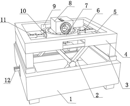
The movable punching machine for planting bars in the above-mentioned patent has the following disadvantages: the weight of the equipment will act on the traveling wheels, and the traveling wheels are not fixed, so the equipment is easy to move when punching holes, causing the drill bit to be easily damaged and affecting the drilling the accuracy of

Method used


Image

  • A drilling device for construction engineering
  • A drilling device for construction engineering
  • A drilling device for construction engineering

Examples


Embodiment Construction

[0029] The technical solution of this patent will be further described in detail below in conjunction with specific embodiments.

[0030] Embodiments of the present patent are described in detail below, examples of which are shown in the drawings, wherein the same or similar reference numerals designate the same or similar elements or elements having the same or similar functions throughout. The embodiments described below by referring to the figures are exemplary and are only used for explaining the patent, and should not be construed as limiting the patent.

[0031] In the description of this patent, it is to be understood that the terms "center", "upper", "lower", "front", "rear", "left", "right", "vertical", "horizontal", The orientation or positional relationship indicated by "top", "bottom", "inner", "outer", etc. is based on the orientation or positional relationship shown in the drawings, and is only for the convenience of describing this patent and simplifying the des...


PUM


Abstract

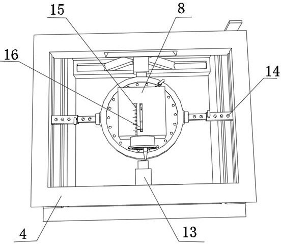
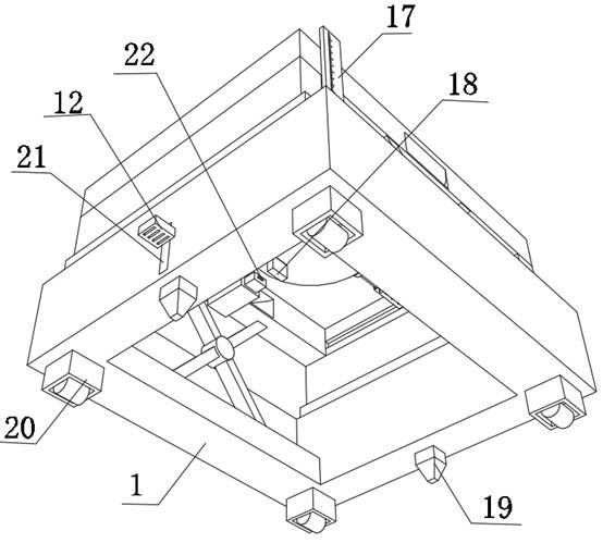
The invention discloses a punching device for construction engineering, which relates to the technical field of construction engineering equipment; in order to solve the problem that the equipment is easy to move through the walking wheels when punching holes; specifically the base, the bottom inner wall of the base is provided with four moving wheels The inner wall of the bottom of the base is slidably connected with two cone columns, and the outer walls on one side of the two cone columns are provided with a moving plate; the outer walls on both sides of the base are provided with sliding grooves, and one side of the two moving plates The outer walls are respectively arranged on the inner walls of the two sliding grooves; two electric telescopic columns are arranged on the top outer wall of the base, and the same fixing seat is arranged on the top outer walls of the two electric telescopic columns. The present invention is provided with structures such as a cone column and a reference plate, and after the equipment is pushed to the working position through the moving wheels, the two moving plates are respectively stepped on, so that the cone column penetrates the ground through the sliding groove, ensuring the safety and stability of the equipment and avoiding operation Equipment movement during the period affects the quality of punching.

Description

technical field [0001] The invention relates to the technical field of construction engineering equipment, in particular to a drilling device for construction engineering. Background technique [0002] There is no need to punch holes all the time in construction projects. The frequency of use of the punch is very high. It is widely used in the reinforcement of building beams, plates, columns, walls, etc., decoration, wall installation, brackets, railings, billboards, air-conditioning outdoor units, and guide rails. , Satellite receiver elevators, steel structure factory buildings, etc. During the construction process, it is necessary to use devices to drill holes in the foundation for subsequent engineering construction. When some existing devices drill holes in the foundation, the hole position is easy to miss, and The straight-line spacing between the holes needs to be drawn in advance and then drilled, which is troublesome. [0003] After retrieval, the Chinese patent ap...

Claims


Application Information

Patent Timeline
Patent Type & Authority Patents(China)
IPC IPC(8): B28D1/14B28D7/00B28D7/02
CPCB28D1/14B28D1/146B28D7/00B28D7/02
Inventor 刘杰唐春园刘长沙陈晓勤
Owner CHINA CONSTR IND & ENERGY ENG GRP CO LTD
Learn More