
Adjustable urban intelligent lighting equipment and control system thereof

An intelligent lighting and adjustable technology, which is applied in the direction of energy-saving lighting, energy-saving control technology, lighting and heating equipment, etc., can solve the problems of incomplete utilization of power resources of street lamps, resource occupation, and low power consumption, and achieve simple structure, Reduce repeated installation and facilitate operation

Inactive Publication Date: 2020-12-01
NANTONG SAVER VICTORIA OPTICAL TECH
View PDF6 Cites 0 Cited by
  • Summary
  • Abstract
  • Description
  • Claims
  • Application Information

AI Technical Summary

Problems solved by technology

However, in the current urban construction of lighting street lamps, special power resources (box-type transformers) are reserved for street lamps. Street lamps do not supply power during the day and supply power at night. Therefore, the power resources allocated to street lamps are not fully utilized, and the overall utilization rate is basically 50%. , and the street lamp only realizes the lighting function, but it occupies a large amount of resources, resulting in a waste of resources. To support the implementation of other equipment, make lighting street lamps as carriers for the construction of smart city facilities

Method used


Image

  • Adjustable urban intelligent lighting equipment and control system thereof
  • Adjustable urban intelligent lighting equipment and control system thereof
  • Adjustable urban intelligent lighting equipment and control system thereof

Examples


Embodiment Construction

[0026] The technical solutions of the present invention will be clearly and completely described below through specific embodiments.

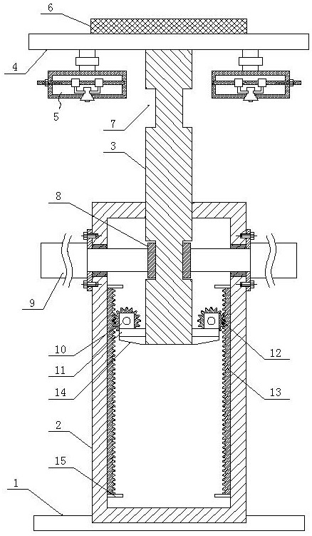
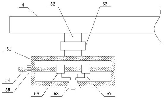
[0027] An adjustable urban intelligent lighting device of the present invention includes a fixed base 1, a first light pole 2, a second light pole 3, a mounting plate 4, a solar panel 6 and a lighting device 5; the specific structure is as follows Figure 1~3 As shown, the fixed base 1 is arranged horizontally, and a first light pole 2 is vertically embedded and fixed in the middle of its upper surface. The first light pole 2 is a hollow structure arranged vertically, and is coaxial on its upper surface. The center is vertically plugged with a second light pole 3, the lower end of which extends vertically downwards to the inside of the first light pole 2, and vertically slides up and down with the inner wall of the first light pole 2. .

[0028] Such as figure 2 , image 3 As shown, electro-hydraulic cylinders 9 are horizontally symmetrically...


PUM


Abstract

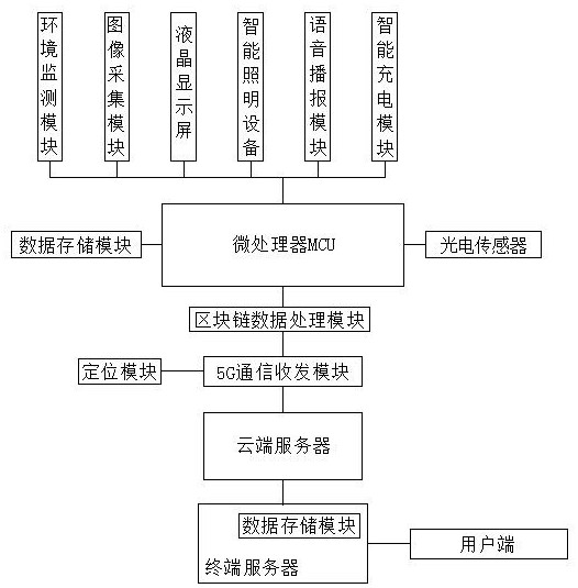
The invention discloses adjustable urban intelligent lighting equipment and a control system thereof. The adjustable urban intelligent lighting equipment comprises a fixed base, a first lamp pole, a second lamp pole, a mounting plate, a solar panel and lighting devices. The first lamp pole is vertically arranged on the upper surface of the fixed base, the first lamp pole is of a hollow structure,the second lamp pole is coaxially inserted into the upper surface of the first lamp pole, and the lower end of the second lamp pole vertically extends downwards into the first lamp pole and is vertically connected with the inner side wall of the first lamp pole in an up-down sliding mode. The mounting plate is horizontally arranged, the middle of the lower surface of the mounting plate is fixedlyconnected with the upper end of the second lamp pole, the solar panel is horizontally arranged on the upper surface of the mounting plate, lighting devices are symmetrically hung on the left side andthe right side of the lower surface of the mounting plate, the lighting devices are electrically connected with the solar panel, and the lighting ends of the lighting devices are vertically arranged downwards. Environment monitoring, image acquisition, information display, voice broadcast and intelligent charging are integrated in the intelligent lighting equipment, so that centralized construction is facilitated, and repeated installation of the equipment is reduced.

Description

technical field [0001] The invention relates to the field of lighting equipment, in particular to an adjustable urban intelligent lighting equipment and a control system thereof. Background technique [0002] Under the current situation of rapid global development, smart city, as the latest concept of future urban development, has been initially put into practice. Smart city is the embodiment of high-speed urban informatization after digital city and smart city, and it is the deep integration of informatization, industrialization and urbanization. In essence, the concept of smart city reflects that urban development requires not only thorough perception, interconnection, and in-depth intelligence in technology, but also the separation of information between urban economy, medical care, transportation, municipal administration, environmental protection, and urban management. , The information systems and systems of each department are basically built independently and manage...

Claims


Application Information

Patent Timeline
Patent Type & Authority Applications(China)
IPC IPC(8): F21S9/03F21V17/12F21V17/16F21V21/02F21V21/10F21V23/00F21V23/04F21V31/00G01D21/02H05B45/00H05B47/19F21W131/103F21Y115/10
CPCF21S9/035F21V21/02F21V21/10F21V17/12F21V17/164F21V31/005F21V23/003F21V23/04H05B45/00H05B47/19G01D21/02F21Y2115/10F21W2131/103Y02B20/40Y02B20/72
Inventor 李晓君陈卫
Owner NANTONG SAVER VICTORIA OPTICAL TECH
Learn More