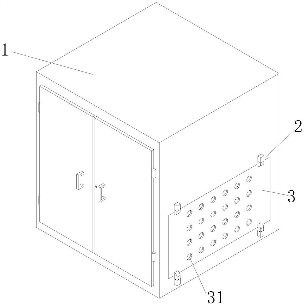
Moisture-proof device for electrical equipment
A technology for electrical equipment and installation slots, applied in substation/distribution device housing, substation/switchgear cooling/ventilation, substation/switch layout details, etc. Difficult to apply and other problems, to achieve the effect of easy cleaning and maintenance, avoiding excessive local moisture absorption, and weakening the dustproof effect
- Summary
- Abstract
- Description
- Claims
- Application Information
AI Technical Summary
Problems solved by technology
Method used
Image

Examples
Embodiment Construction
[0021] The following will be combined with the accompanying drawings in the embodiments of the present invention, the technical solution in the embodiments of the present invention will be described clearly and completely, it is clear that the embodiments described are only a part of the embodiment of the present invention, not all embodiments.
[0022] Examples of the embodiments are shown in the accompanying drawings, wherein the same or similar labels from beginning to end represent the same or similar elements or elements with the same or similar functions. The embodiments described below by reference to the accompanying drawings are exemplary and are intended to be used to explain the present invention, and cannot be construed as a limitation of the present invention.
[0023] In the description of the present invention, it is to be understood that the terms "center", "longitudinal", "transverse", "length", "width", "thickness", "up", "down", "front", "back", "left", "right",...
PUM
 Abstract
Description
Claims
Application Information
PatSnap Eureka turns technology decisions into work you can execute. Powered by our Innovation Knowledge Graph, it runs expert workflows across engineering, life sciences, materials and intellectual property. Get your review-ready output in minutes.


