Time synchronization method for multi-antenna system

A multi-antenna system and time synchronization technology, applied in radio transmission systems, time-division multiplexing systems, transmission systems, etc., can solve the problems of increasing system costs, wasting channel resources, and decreasing link throughput, achieving high reliability Expandability, improve time synchronization accuracy, and improve stability

Active Publication Date: 2022-07-08
10TH RES INST OF CETC
View PDF11 Cites 0 Cited by
  • Summary
  • Abstract
  • Description
  • Claims
  • Application Information

AI Technical Summary

Problems solved by technology

[0004] In the time synchronization system between wireless communication members, one channel is often designated as a common channel, and the remaining channels are used as data channels. All nodes exchange control information on the common channel, and obtain available data channels to transmit data through contention. , when the number of channels used is small, dedicated use of a common control channel wastes channel resources
Since the backbone node has multiple directional antennas to transmit and receive at the same time, if a node uses the same channel to transmit and receive data on different directional antennas, it will cause interference between channels and reduce the throughput of each link.
Moreover, multiple links from one node use the same channel. In order to avoid channel interference, high requirements are placed on the antenna, which also increases the difficulty of system synchronization and increases the cost of the system.
When the number of channels used is large, all nodes compete for data channels through a common control channel, making the control channel a bottleneck and channel resources cannot be fully utilized.
[0005] Due to the large size of the aircraft in the aviation communication system, the antennas are distributed in various parts of the aircraft. The channels of different antennas are due to factors such as differences in the internal wiring of the aircraft and differences in the RF circuits of each transceiver front-end. The RTT method shows that if the paths of the RTT query message and the response message use different antennas, the delay time difference between antenna transmission and reception will affect the final time synchronization accuracy

Method used


Image

  • Time synchronization method for multi-antenna system
  • Time synchronization method for multi-antenna system

Examples


Embodiment Construction

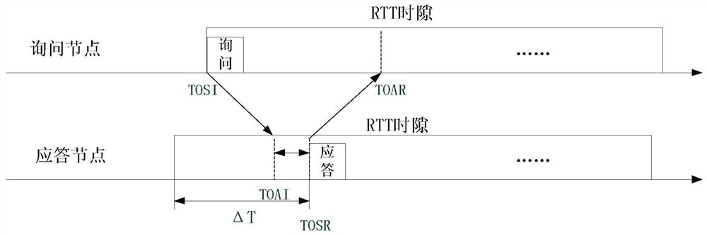
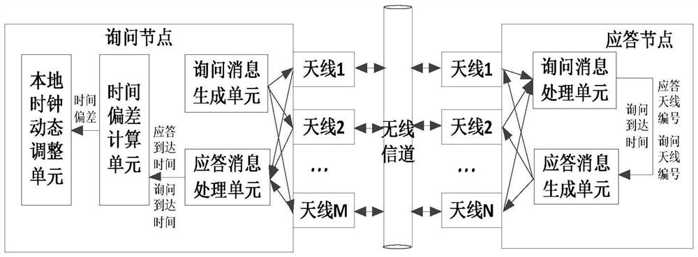
[0015] see figure 1 . According to the present invention, a query node with M antennas and a response node with N antennas are constructed in a multi-antenna system, at least one query node and response node periodically exchange query messages and response messages according to time synchronization, and the query node The inquiry message is transmitted through multiple antennas, and the inquiry message is sent through M antennas to generate M wireless signals; the answering node listens to the wireless channel and receives the wireless signal at the same time, and measures the signal arrival time TOAI when receiving the inquiry message, and the answering node detects the To the arrival time of M×N messages, select S arrival time points of the optimal signal according to the selection criterion of the optimal signal, record the antenna number p of the query node and the antenna number q of the response node corresponding to this time point, and the response node receives the m...


PUM


Abstract

The invention discloses a time synchronization method for a multi-antenna system, and aims to provide a time synchronization method that can effectively improve the time synchronization accuracy. The present invention is realized by the following technical solutions: an inquiry node with M antennas and a response node with N antennas are constructed in a multi-antenna system, and the inquiry node sends M wireless signals through M antennas; the response node detects M× N message arrival times, select S arrival time points of the optimal signal, and return S arrival time points carrying records at a specified time in a time slot; the query node selects and query messages according to the received response messages The arrival time of the response message matching the arrival time, calculate the time deviation between the query node and the response node according to the selected query message arrival time point and the response message arrival time point, and adjust the local clock and query node time to complete the response node and query node membership time synchronization between.

Description

technical field [0001] The invention relates to a multi-antenna system time synchronization method which is applied to a time synchronization system between communication members in the multi-antenna wireless communication field and improves the time synchronization precision. Background technique [0002] The time synchronization system is a system that can receive external time reference signals and output time synchronization signals and time information according to the required time accuracy. It can align and synchronize other clocks in the network. Technical measures Implement high-precision "matching tables" for clocks in the network. To realize the time synchronization system, the first is to establish a time synchronization protocol, including defining the format of the time stamp, the method of transmitting the time stamp and extracting the correction value, etc., and then the technical realization based on the protocol, including the time correction technology and...

Claims


Application Information

Patent Timeline
Patent Type & Authority Patents(China)
IPC IPC(8): H04J3/06H04B7/0413
CPCH04J3/0644H04J3/0682H04B7/0413Y02D30/70
Inventor 焦志海卢华李晓光魏宝圆唐李杨熊竟宇
Owner 10TH RES INST OF CETC
Why Eureka
Try Eureka