

Time synchronization method and device
A time synchronization and clock synchronization technology, applied in the synchronization field, can solve problems such as being easily affected by network topology changes and poor time synchronization accuracy, so as to solve the problem of poor time synchronization accuracy, improve time accuracy and stability, and reduce the impact Effect
- Summary
- Abstract
- Description
- Claims
- Application Information
AI Technical Summary
Problems solved by technology
Method used
Image

Examples
Embodiment 1
[0024] An application scenario of the embodiment of the present application is: a network element completes frequency synchronization through a selected frequency synchronization algorithm, and then uses the operation result of the frequency synchronization algorithm to realize network time synchronization. Wherein, the selected frequency synchronization algorithm is Synchronization Status Message algorithm (SSM, Synchronization Status Message) in this solution. The implementation principle of using the results of the frequency synchronization algorithm to realize the time synchronization of the network is as follows: the master-slave relationship (that is, the port status) obtained based on the SSM algorithm, through the protocol interaction method ( Figure 6 The interaction about the PLL in the middle) is locked on the network element (or locked on the network element port), and then based on this (calculated by SSM) port status, the network time synchronization is realized ...
Embodiment 2
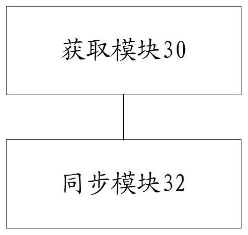
[0053] In this embodiment, a time synchronization device is also provided, which is used to implement the above embodiments and preferred implementation modes, and what has been described will not be repeated. As used below, the term "module" may be a combination of software and / or hardware that realizes a predetermined function. Although the devices described in the following embodiments are preferably implemented in software, implementations in hardware, or a combination of software and hardware are also possible and contemplated.
[0054] image 3 is a structural block diagram of a time synchronization device according to an embodiment of the present invention, such as image 3 As shown, the device includes:
[0055] The obtaining module 30 is configured to obtain a clock synchronization result based on a network element determined through a clock synchronization algorithm. Optionally, the clock synchronization result includes: a port status of a specified port in the net...
Embodiment 3
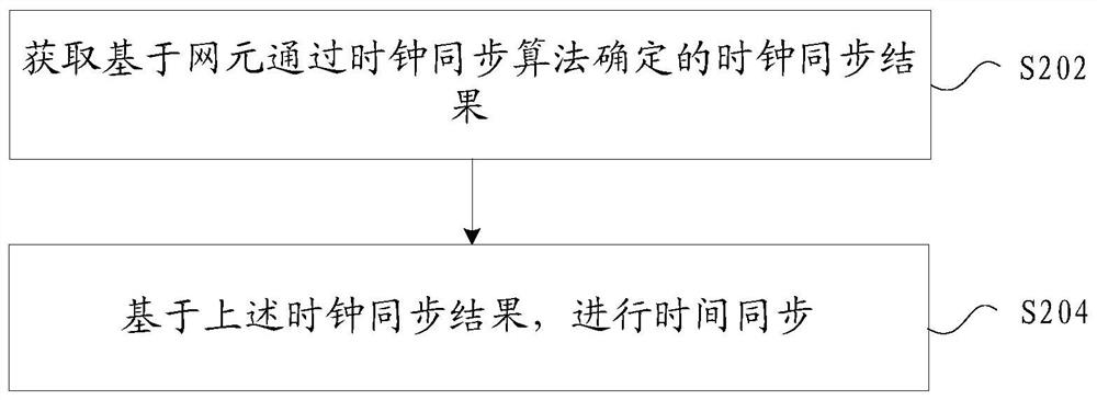
[0064] The time synchronization method provided in this embodiment includes the following processing steps:
[0065] Step 501: The clock node extracts the best master clock of SSM according to the synchronization status information, and the best master clock of SSM is used as the best master clock for frequency synchronization;
[0066] Step 501 further includes:
[0067] Such as Figure 4 Shown: The clock synchronization network is established between the devices in the form of a ring network, and the main link (SEC1--SEC2------SEC6) and the backup link (SEC1--SEC6------SEC2) are completed. ) clock source configuration. The illustration only describes the configuration of a single ring, and a large-scale network is configured in layers according to the core layer, aggregation layer, and access layer. Figure 4 The meanings represented by SEC or EEC in the SEC identify the network device in the embodiment of the present application, which meets the clock requirements of a cla...
PUM
 Abstract
Description
Claims
Application Information