
Vertical and horizontal dual-purpose fire extinguisher

A technology for both vertical and horizontal use and fire extinguisher, which is used in fire rescue and other directions

Active Publication Date: 2020-12-04
江山智安消防设备有限公司
View PDF6 Cites 0 Cited by
  • Summary
  • Abstract
  • Description
  • Claims
  • Application Information

AI Technical Summary

Problems solved by technology

[0003] The invention provides a vertical and horizontal dual-purpose fire extinguisher capable of spraying both in the vertical state and in the flat state, which solves the problem that the existing fire extinguishers can only spray in the vertical state

Method used


Image

  • Vertical and horizontal dual-purpose fire extinguisher
  • Vertical and horizontal dual-purpose fire extinguisher
  • Vertical and horizontal dual-purpose fire extinguisher

Examples


Embodiment 1

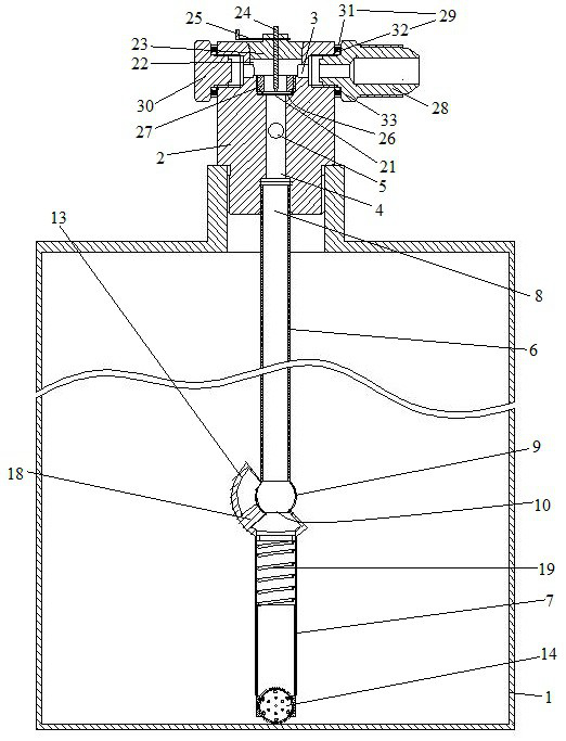
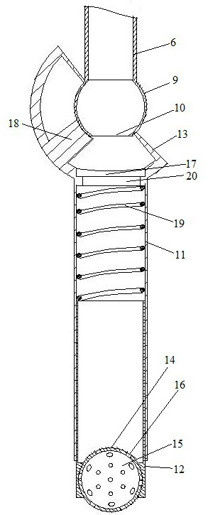
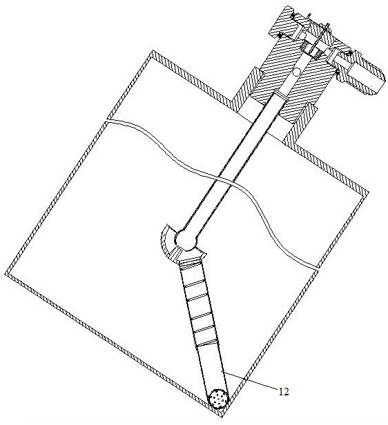
[0026] Embodiment one, see Figure 1 to Figure 4A vertical and horizontal fire extinguisher includes a fire extinguisher control valve and a fire extinguisher cylinder 1 with a valve connection port at the upper end. The fire extinguishing agent control valve includes a valve body 2 provided with a flow passage on-off control mechanism. The valve body is thread-tightly connected in the valve connection port. The valve body is provided with the fire extinguishing agent outlet 3 of the valve body part, the fire extinguishing agent inlet 4 of the valve body part and the pressure gauge connection interface 5, and the pressure gauge is connected in the pressure gauge connection during use. The fire extinguishing agent outlet of the valve body is communicated with the fire extinguishing agent inlet of the valve body through the fire extinguishing agent outflow channel. The flow channel channel control mechanism is used to make the connection between the fire extinguishing agent ou...

Embodiment 2

[0029] Embodiment 2 is different from Embodiment 1 in that: the junction of the side wall and the bottom wall of the fire extinguisher cylinder is provided with a support ring 34 extending along the circumferential direction of the fire extinguisher cylinder and located in the fire extinguisher cylinder for supporting and supporting rolling balls. A mirror layer is provided on the support surface of the support ring. An anti-off block 35 is provided on the thimble to prevent the thimble from falling off the connecting seat, and the anti-off block is located between the connecting seat and the partition film. The thimble is sleeved with a thimble drive spring 36 that drives the thimble to move toward the partition film so that the thimble pierces the partition film. Under the action of the thimble drive spring, the limit pin abuts against the connecting seat.


PUM


Abstract

The invention relates to a vertical and horizontal dual-purpose fire extinguisher comprising a fire extinguisher cylinder with a valve connector at the upper end and a fire extinguishing chemical control valve connected to the fire extinguisher cylinder, a valve body is connected with a fire extinguishing chemical output pipe located in the fire extinguisher cylinder, the fire extinguishing chemical output pipe comprises an upper section and a lower section, a spherical connector is arranged at the lower end of the upper section, the lower end of the lower section is provided with a lower section fire extinguishing chemical inlet, the upper end of the lower section is provided with a connecting cover, the connecting cover is in spherical surface fit with the spherical connector and is capable of rotationally and hermetically sleeving the spherical connector, and an ejector block supported on the spherical connector in a spherical surface fit manner is arranged in the connecting cover.The vertical and horizontal dual-purpose fire extinguisher provided by the invention not only can be used for spraying in a vertical state, but also can be used for spraying in a horizontal state, sothat the problem that an existing fire extinguisher can only be used for spraying in the vertical state is solved.

Description

technical field [0001] The invention relates to a fire extinguisher, in particular to a vertical and horizontal fire extinguisher. Background technique [0002] A fire extinguisher is a portable fire extinguishing tool. Chemicals are placed in the fire extinguisher to put out the fire. Fire extinguishers are one of the common fire prevention facilities. They are stored in public places or places where fires may occur. Different types of fire extinguishers contain different ingredients and are specially designed for different fire causes. The substrate structure of the fire extinguisher includes a fire extinguisher cylinder and a valve assembly connected to the fire extinguisher cylinder. The valve assembly includes a valve body and a flow channel on-off control mechanism. The valve body is provided with a fire extinguisher outlet, a fire extinguisher inlet and a pressure gauge connection. interface, the fire extinguishing agent outlet and the fire extinguishing agent inlet...

Claims


Application Information

Patent Timeline
Patent Type & Authority Applications(China)
IPC IPC(8): A62C13/64A62C13/76
CPCA62C13/64A62C13/76
Inventor 周孝卫
Owner 江山智安消防设备有限公司
Learn More