Gluing piece and gluing device of bookbinding machine

A binding machine and plastic parts technology, applied in the field of binding machines, can solve the problems of large horizontal space, large overall volume, not suitable for office use, etc., and achieve the effect of compact layout and small volume

Pending Publication Date: 2020-12-04
DONGGUAN ELITE ELECTRIC HARDWARE PRODUCT CO LTD +1
View PDF0 Cites 0 Cited by
  • Summary
  • Abstract
  • Description
  • Claims
  • Application Information

AI Technical Summary

Problems solved by technology

In the above-mentioned rolling and gluing mode, the moving distance of the sheets of paper is very long, which makes the length of the whole binding machine relatively large, thereby making the layout of the whole machine unreasonable, and taking up a large horizontal space, resulting in a large overall volume, which is not convenient. Great for office use

Method used


Image

  • Gluing piece and gluing device of bookbinding machine
  • Gluing piece and gluing device of bookbinding machine
  • Gluing piece and gluing device of bookbinding machine

Examples


Embodiment Construction

[0051] In order to describe the technical content, structural features, and achieved effects of the present invention in detail, the following will be described in detail in conjunction with the embodiments and accompanying drawings.

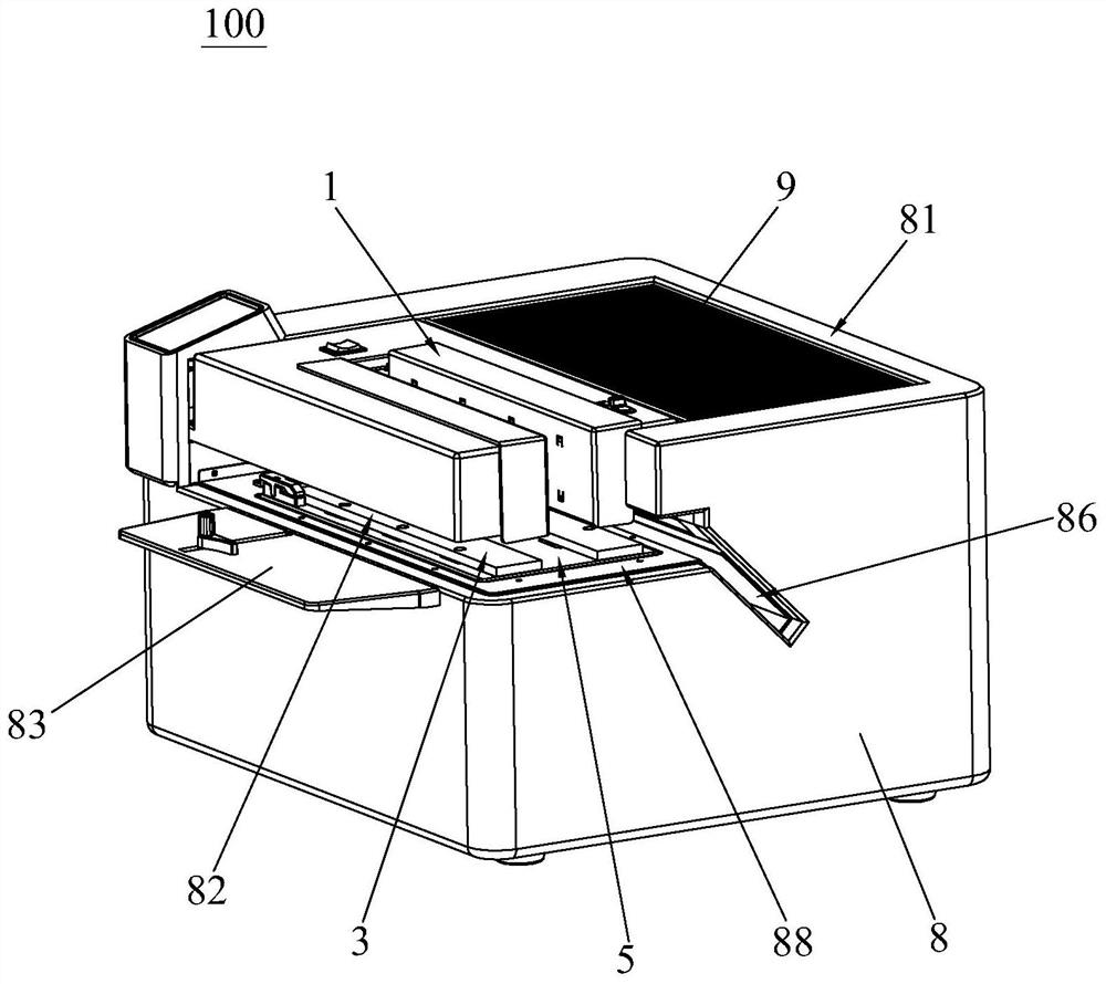
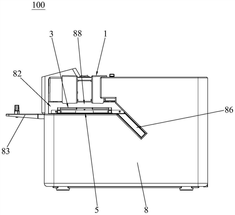
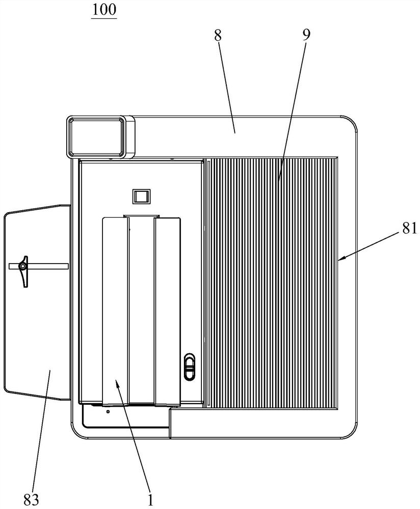
[0052] Such as Figure 1 to Figure 7As shown, the binding machine 100 of the present invention includes a paper clamping device 1 , a gluing device 2 , a case binding device 3 , a translational driving mechanism 4 , a platform 5 , a fixing bracket 6 , a lifting driving mechanism 7 and a housing 8 . The upper side of the housing 8 is an opening 81, and the paper clamping device 1, gluing device 2, case binding device 3, translational driving mechanism 4, platform 5, fixed bracket 6 and lifting driving mechanism 7 are all arranged in the housing. 8 within. Wherein, the paper clamping device 1 is located at the opening 81 of the housing 8 . The case binding device 3 is vertically arranged with the paper clamping device 1 , and the case binding de...


PUM


Abstract

The invention discloses a gluing device of a bookbinding machine. The gluing device comprises a gluing piece, a gluing driving mechanism and a glue tank used for loading glue, wherein the surface of the gluing piece is provided with a glue dipping face, the gluing piece is arranged in the glue tank, and the gluing driving mechanism drives the gluing piece to descend and enter the glue tank or drives the gluing piece to ascend and extend out of the glue tank. The gluing device has the advantages that vertical gluing is achieved, the layout of the bookbinding machine is more compact, and the size is smaller. In addition, the invention further discloses a gluing piece and the gluing device.

Description

technical field [0001] The invention relates to a binding machine, in particular to a gluing piece and a gluing device of the binding machine. Background technique [0002] Existing paper binding machines generally include three parts: a paper clamping device, a gluing device and a cover covering device, and the paper clamping device, the gluing device and the cover covering device are arranged horizontally in sequence. During glue binding, the paper sheets are aligned with the reference platform of the paper clamping device, and then the paper clamping device clamps the stacked paper sheets; then the paper clamping device drives the paper sheets to move laterally to the top of the gluing device, and the paper is aligned by the gluing device Glue on the sheet; finally, the paper clamping device drives the sheet of paper to move horizontally to the top of the cover wrapping device, and wraps the cover of the sheet of paper through the cover wrapping device. [0003] Wherein,...

Claims


Application Information

Patent Timeline
Patent Type & Authority Applications(China)
IPC IPC(8): B05C1/02B05C11/10B42C9/00
CPCB05C1/02B05C11/1002B05C11/1039B05C11/1042B42C9/00
Inventor 陆学中覃鹏张云华
Owner DONGGUAN ELITE ELECTRIC HARDWARE PRODUCT CO LTD
Why Eureka
Try Eureka