Hot runner protection structure and guide column thereof

A hot runner plate and guide post technology, applied in the field of molds, can solve the problems of affecting the guiding function of guide posts, easily damaged guide posts, and deformation of guide post ends, so as to improve service life, improve guiding performance, and avoid wear and deformation Effect

Inactive Publication Date: 2016-11-09
台州市黄岩亿德塑模有限公司
View PDF5 Cites 1 Cited by
  • Summary
  • Abstract
  • Description
  • Claims
  • Application Information

AI Technical Summary

Problems solved by technology

[0005] However, in the above-mentioned method, although the guide post not only plays a role in the convenient installation of the hot runner plate and the fixed mold, but also plays a role in protecting the hot nozzle when the hot runner plate is placed, but the guide post directly supports its entire The way of the weight of the fixed mold seat plate and the hot runner plate is easy to damage the guide post, so that the end of the guide post is deformed, thus affecting the guiding function of the guide post

Method used


Image

  • Hot runner protection structure and guide column thereof
  • Hot runner protection structure and guide column thereof
  • Hot runner protection structure and guide column thereof

Examples


Embodiment 1

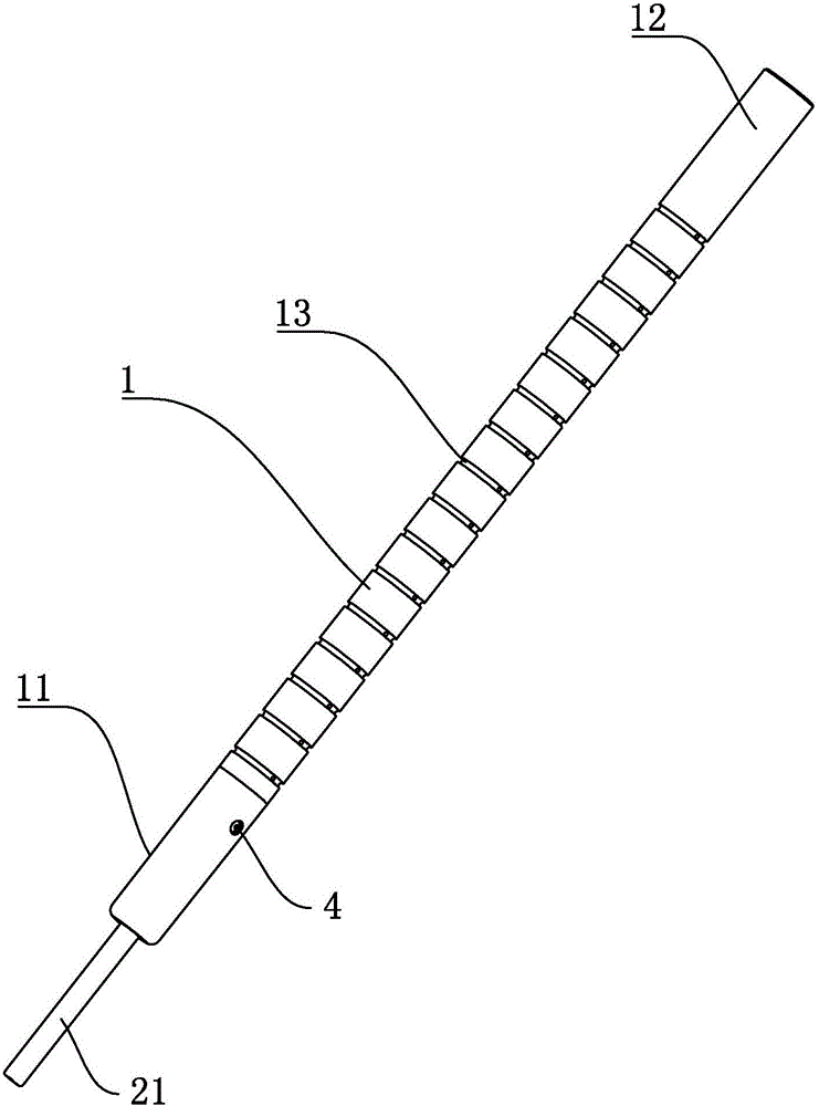
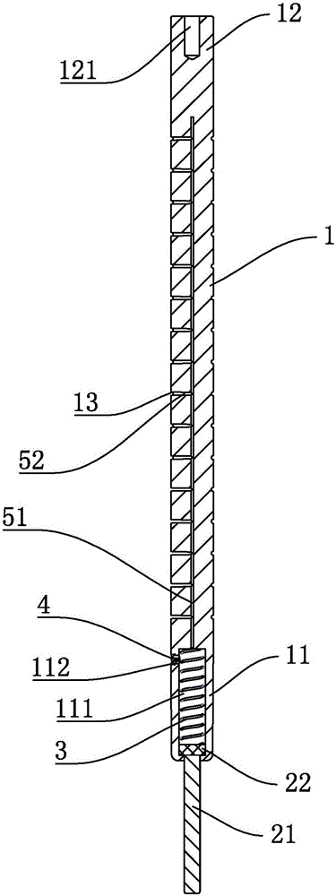
[0037] Embodiment 1, a guide post, see attached figure 1 and 2 , the guide column includes a column body 1, one end of the column body 1 is provided with a mounting end 12, and the end of the mounting end 12 is provided with a mounting threaded hole 121; the other end of the column body 1 is an insertion end 11, through which the The guide post cooperates with the guide hole to realize the guide function; the end of the guide part is provided with a support foot, which can be directly fixed on the end of the insertion end 11 or can be divided into two parts as in the first embodiment. It is a sliding block 22 and a supporting foot, wherein the sliding block 22 cooperates and slides in the sliding cavity 111 of the insertion end 11, and a spring 3 for restoring is provided between the sliding block and the bottom of the sliding cavity 111; For details, see attached figure 2 , an oil inlet hole 112 communicating with the sliding chamber 111 is provided on the subject side wal...

Embodiment 2

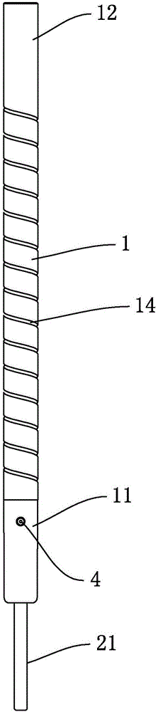
[0039] Embodiment 2, a guide post, see attached image 3 and 4 , the difference from the first embodiment is that the annular oil groove 13 originally provided on the outer wall of the cylinder 1 is replaced with a spiral oil groove 14 surrounding the cylinder 1, and the first oil guide 51 and the spiral oil groove 14 pass through The third oil guide channel is connected. The third oil guide channel is arranged in an axially spaced manner along the first oil guide channel 51. If the length is long, even if the oil groove has burrs and other phenomena, because a certain angle is not perpendicular to the guiding direction, but has a certain angle, the influence on the guiding accuracy is smaller than that of the horizontal annular oil groove 13 .

Embodiment 3

[0040] Embodiment 3, a hot runner protection structure, see attached Figure 5 , the guide column in the first embodiment is used here, and of course the guide column in the second embodiment can also be selected. The hot runner protection structure includes a fixed die seat plate 6 and a hot runner plate 7. The hot runner plate 7 is provided with For the hot runner, the hot runner 8 of the hot runner protrudes through the hot runner plate 7 .

[0041] When installing the hot runner protection structure and the fixed die, the guide posts are installed in alignment with the guide holes on the fixed die, so as to realize the convenient installation effect of the hot runner protection structure and the fixed die. The dry friction problem and the vacuum suction problem are avoided when inserting the guide hole of the fixed mold; after the hot runner protection structure is separated from the fixed mold, the overall support of the hot runner protection structure can be carried out ...


PUM


Abstract

The invention discloses a guide column. The guide column comprises a column body. One end of the column body is an insertion end. A supporting foot with the diameter being smaller than that of the insertion end is arranged at the end socket of the insertion end in the axial direction of the column body, and the supporting foot extends out of the insertion end. When the guide column is used as a bearing part to support objects, the supporting foot arranged at the insertion end is supported on the ground, and the insertion end of the column body is prevented from making contact with the ground directly, so that the condition that the insertion end bears excessive weight and then is deformed, and consequently the normal guiding function of the guide column is influenced is avoided; and the diameter of the supporting foot is smaller than that of the insertion end, the support foot does not interfere a guide hole when the guide column is used, and thus the normal guide function of the guide column can be achieved.

Description

technical field [0001] The invention relates to the technical field of molds, and more particularly, to a hot runner protection structure and a guide pillar thereof. Background technique [0002] For injection molding of multi-cavity or large-shaped injection parts in one mold, in order to improve the utilization rate of raw materials and reduce the waste of gate materials, molds with hot runner system are mostly used. The hot runner is basically set in the front mold part. The setting method is usually fixed mold, hot runner plate and fixed mold seat plate. The hot runner system is set in the hot runner plate, and then the hot runner plate is fixed with the fixed mold seat plate. On the fixed mold Then there is a cavity for installing the hot runner plate. After the fixed mold is installed on the fixed mold seat plate, the hot runner plate cooperates with the cavity; the hot runner system will be provided with a nozzle, and the nozzle will enter the fixed mold after passing...

Claims


Application Information

Patent Timeline
Patent Type & Authority Applications(China)
IPC IPC(8): B29C45/26B29C45/83
CPCB29C45/2606B29C45/83
Inventor 李佳
Owner 台州市黄岩亿德塑模有限公司
Why Eureka
Try Eureka