Inking device applied to printer

A printing press and ink storage tank technology, applied in printing presses, general parts of printing machinery, inking devices, etc., can solve problems such as affecting printing quality, uneven distribution of ink, and inability to effectively adjust the distance between the ink scraping device and the ink roller, etc. to improve the mixing effect

Active Publication Date: 2020-12-04
浙江恒茂泰数码科技股份有限公司
View PDF7 Cites 3 Cited by
  • Summary
  • Abstract
  • Description
  • Claims
  • Application Information

AI Technical Summary

Problems solved by technology

[0003] The main structure of the gravure printing machine consists of five parts: paper feeding, ink feeding, printing, drying, and paper delivery. The printing part is the main process. In the printing part, the ink roller is rotated in the ink pool to supply ink and Transmission, the uniformity of the ink in the ink pool will change to varying degrees due to gravi...

Method used


Image

  • Inking device applied to printer
  • Inking device applied to printer
  • Inking device applied to printer

Examples


Embodiment 1

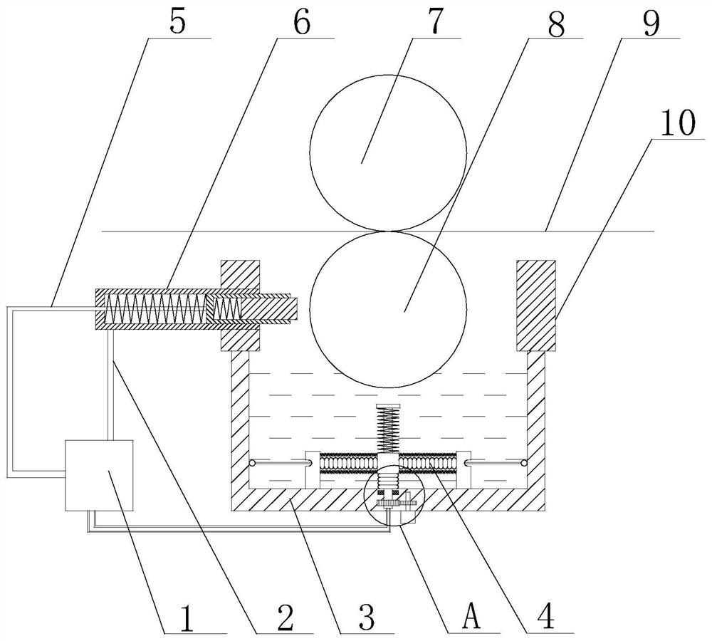
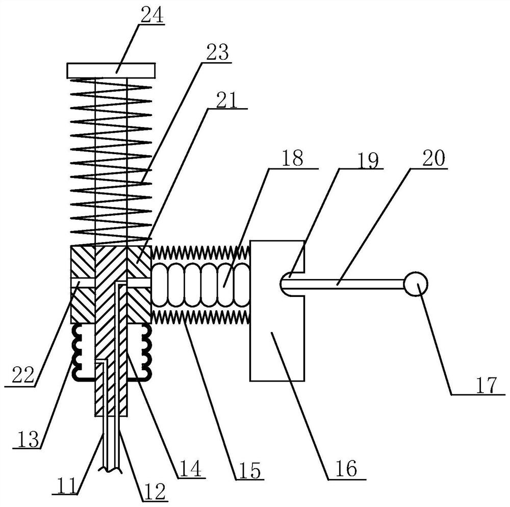
[0043] Such as Figure 1 to Figure 9 As shown, the present invention comprises impression cylinder 7 and printing plate cylinder 8, and described impression cylinder 7 is positioned at the top of printing plate cylinder 8, also comprises air pump 1, motor 30, ink reservoir, and described ink reservoir comprises the lower pool body of circular structure 3 and an upper pool body 11 of rectangular structure, the upper pool body 3 is located above the lower pool body 3, and the inner bottom of the lower pool body 3 is provided with a stirring assembly 4, and the stirring assembly 4 includes a stirring shaft 14, a first telescopic tube 13. Several second telescopic tubes 18, movable blocks 21 and several stirring plates 16, the stirring shaft 14 is connected to the inner bottom of the lower pool body 3 in rotation, the motor 30 can drive the stirring shaft 14 to rotate in the lower pool body 3, the first telescopic The tube 13 is sleeved on the stirring shaft 14, and one end of the...

Embodiment 2

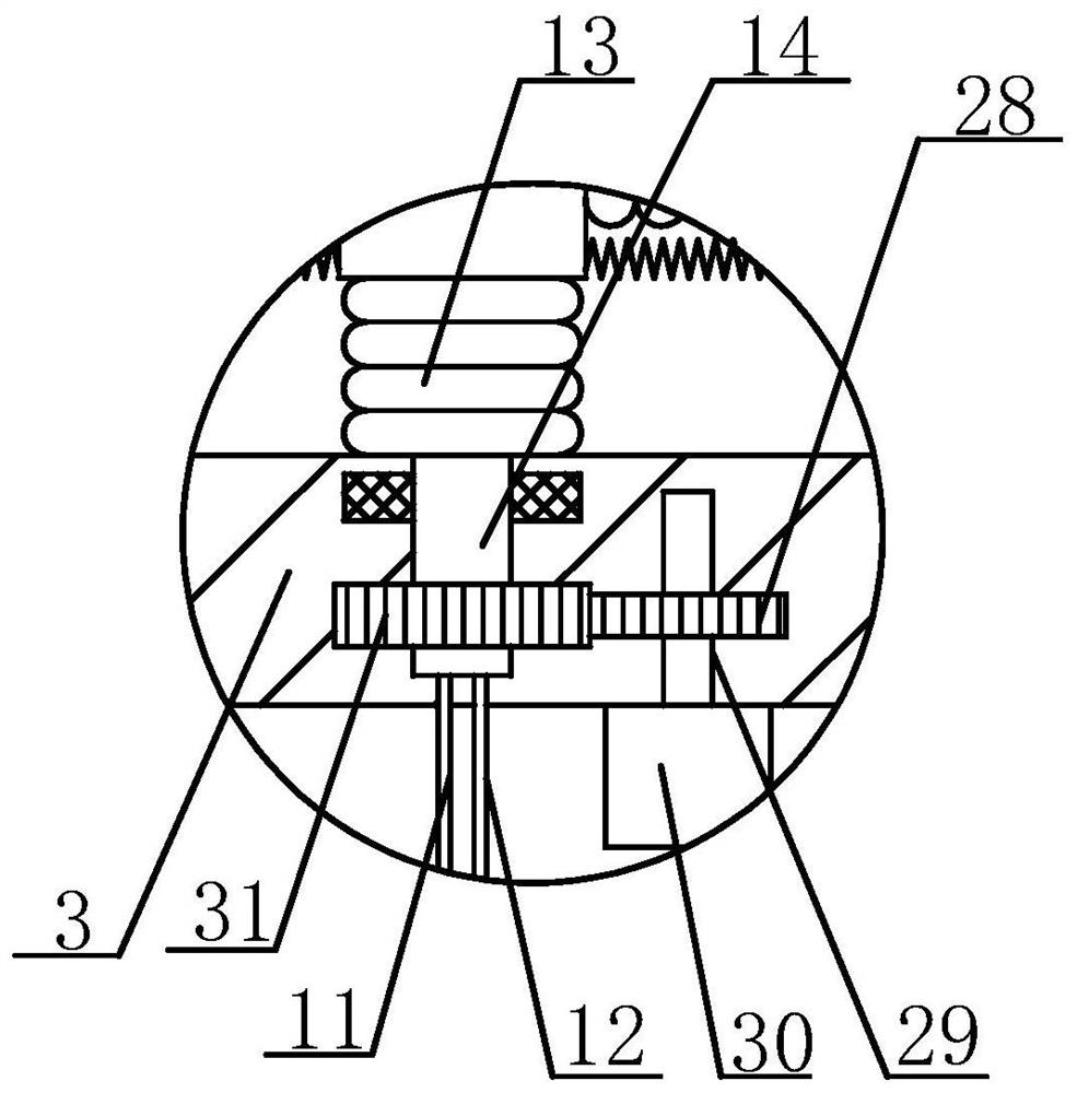
[0047] On the basis of Embodiment 1, the output end of the motor 30 extends into the lower pool body 3, the output shaft 29 of the motor 30 is provided with the first transmission gear 28, and the stirring shaft 14 is also provided with the first transmission gear. The tooth 28 meshes with the second transmission tooth 31 .

Embodiment 3

[0049] On the basis of Embodiment 1, a limit plate 24 is also provided on the top of the stirring shaft 14, a second elastic member 23 is also provided on the stirring shaft 14, and the second elastic member 23 is sleeved on the stirring shaft 14, and The second elastic member 23 is located between the limiting plate 24 and the movable block 21 .


PUM


Abstract

The invention discloses an inking device applied to a printer. The inking device comprises an impression cylinder and a plate cylinder, and further comprises an air pump, a motor and an ink storage pool; the ink storage pool comprises a lower pool body and an upper pool body; a stirring assembly is arranged at the inner bottom of the lower pool body; the stirring assembly comprises a stirring shaft, a first telescopic pipe, a plurality of second telescopic pipes, a movable block and a plurality of stirring plates; an ink scraping assembly is arranged on one side of the upper pool body and comprises a fixing plate, a first scraping plate and a plurality of second scraping plates; the fixing plate horizontally penetrates through the upper pool body; a first square hole matched with the firstscraping plate is further formed in the end face, located in the direction of the upper pool body, of the fixing plate; the first scraping plate is located in the first square hole; and second squareholes are further formed in the first scraping plate. According to the inking device applied to the printer, printing ink stored in the ink storage pool can be stirred, the requirement for stirring the printing ink of different depths in the ink storage pool can be met, the stirring effect of the printing ink is improved, and meanwhile the ink feeding amount of a printing stock can be rapidly adjusted through the ink scraping assembly.

Description

technical field [0001] The invention relates to the technical field of printing, in particular to an inking device applied to a printing machine. Background technique [0002] Gravure printing is a printing method in which the inked part of the printing plate is concave. By applying ink to the concave graphic part of the printing plate, the excess ink is removed by a doctor blade or other methods, and then under the action of printing pressure, the ink is transferred to the substrate to complete the printing process. Gravure printing has clear layers, thick and bright ink layer, uniform ink color, can truly reproduce the effect of the original manuscript, and the printing speed is fast. It is one of the most widely used printing methods at present. [0003] The main structure of the gravure printing machine consists of five parts: paper feeding, ink feeding, printing, drying, and paper delivery. The printing part is the main process. In the printing part, the ink roller is ...

Claims


Application Information

Patent Timeline
IPC IPC(8): B41F31/07B41F31/03B41F31/04
CPCB41F31/03B41F31/04B41F31/07B41P2231/00
Inventor 李凤英
Owner 浙江恒茂泰数码科技股份有限公司
Why Eureka
Try Eureka