Control method and device of electric power-assisted braking system and vehicle

An electric power assist and braking system technology, applied in the field of vehicles, can solve the problems of driving danger, air entering the brake pipeline, soft braking, etc., and achieve the effect of avoiding driving danger

Inactive Publication Date: 2020-12-04
上海拿森汽车电子有限公司
View PDF12 Cites 3 Cited by
  • Summary
  • Abstract
  • Description
  • Claims
  • Application Information

AI Technical Summary

Problems solved by technology

[0002] Traditional vehicles are equipped with traditional vacuum boosters. The purely mechanical booster system cannot monitor the status of the vehicle from the perspective of the entire vehicle, and cannot send an alarm when the vehicle is in an under-load state, that is, the brake

Method used


Image

  • Control method and device of electric power-assisted braking system and vehicle
  • Control method and device of electric power-assisted braking system and vehicle
  • Control method and device of electric power-assisted braking system and vehicle

Examples


Embodiment Construction

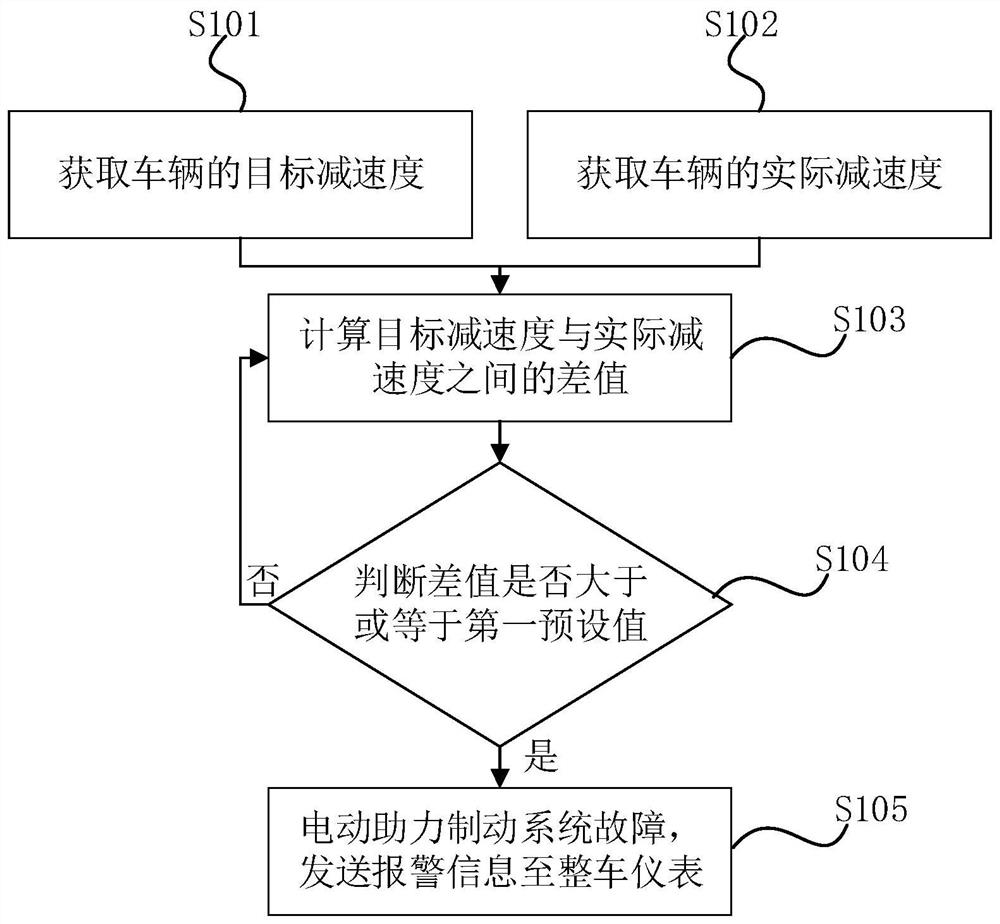
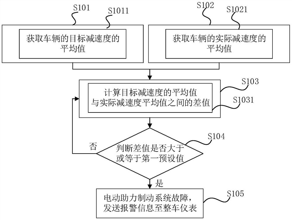
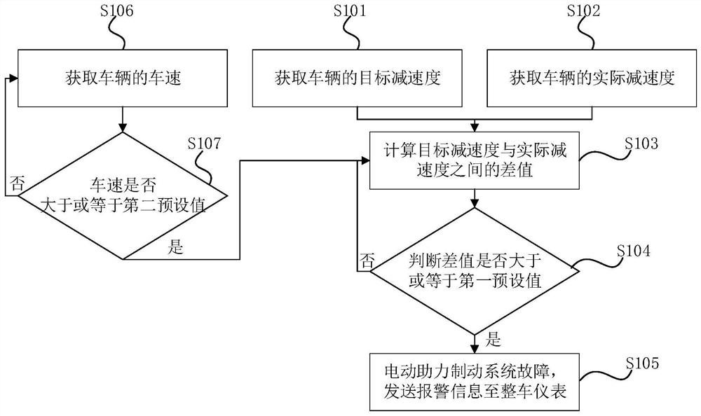
[0077] The present invention will be further described in detail below in conjunction with the accompanying drawings and embodiments. It should be understood that the specific embodiments described here are only used to explain the present invention, but not to limit the present invention. In addition, it should be noted that, for the convenience of description, only some structures related to the present invention are shown in the drawings but not all structures.

[0078] figure 1 It is a flow chart of the control method of the electric power assist braking system according to the embodiment of the present invention. Such as figure 1 As shown, the control method of the electric power-assisted braking system includes the following steps:

[0079] S101, acquiring the target deceleration of the vehicle;

[0080] It should be noted that there is a one-to-one correspondence between the target deceleration of the vehicle and the opening of the brake pedal. The larger the openin...


PUM


Abstract

The invention discloses a control method of an electric power-assisted braking system. The control method comprises the following steps that of acquiring target deceleration of a vehicle; obtaining the actual deceleration of the vehicle; calculating a difference value between the target deceleration and the actual deceleration; judging whether the difference value is greater than or equal to a first preset value or not; and if the difference value is greater than or equal to the first preset value, and the electric power-assisted braking system breaks down, sending alarm information to a wholevehicle instrument so that when the vehicle is in an under-load state, a driver is warned in advance, the driver takes response measures, and driving danger is avoided. The invention further discloses a control device of the electric power-assisted braking system and the vehicle.

Description

technical field [0001] The embodiments of the present invention relate to the technical field of vehicles, and in particular to a control method and device for an electric power-assisted braking system and a vehicle. Background technique [0002] Traditional vehicles are equipped with traditional vacuum boosters. The purely mechanical booster system cannot monitor the status of the vehicle from the perspective of the entire vehicle, and cannot send an alarm when the vehicle is in an under-load state, that is, the brake fluid in the brake system of the vehicle in a sealed state leaks , or air enters the brake pipeline, which will cause the brake to be soft and in an under-load state. At this time, if the driver performs a braking operation, it will cause the driver to panic and cause driving danger. Contents of the invention [0003] The invention provides a control method, a device and a vehicle of an electric power-assisted braking system, so as to realize an early warnin...

Claims


Application Information

Patent Timeline
IPC IPC(8): B60T17/22B60K35/00
CPCB60T17/22B60K35/00
Inventor 陶喆范鹏魏曦朱心放刘海珍张彦朝
Owner 上海拿森汽车电子有限公司
Why Eureka
Try Eureka